Clip Device and Laryngeal Mask Airway

a technology of laryngeal mask and clip device, which is applied in the field of medical instruments, can solve the problems of failure to install the lma, user may be bitten by the patient,

Inactive Publication Date: 2009-08-06
CHEN TIEN SHENG +1
View PDF11 Cites 18 Cited by
  • Summary
  • Abstract
  • Description
  • Claims
  • Application Information

AI Technical Summary

Problems solved by technology

Accordingly, during the installation of an LMA, users always have to insert their finger(s) (especially their index fingers) into a patient's mouth to pass the soft, inconvenient LMA through the upper jaw because of the obstruction caused by the patient's tongue.
In general, this displacement of fingers may cause two problems.
First, there is the risk that the user may be bitten by the patient during the installation of an LMA.
Second, in a case where a patient's oral space is overly small, which may be caused by an overly small mouth, an overly tight jaw joint, or an overly thick tongue, a user may encounter difficulty inserting his / her finger(s) into the patient's mouth, resulting in failure to install the LMA.

Method used


Image

  • Clip Device and Laryngeal Mask Airway
  • Clip Device and Laryngeal Mask Airway
  • Clip Device and Laryngeal Mask Airway

Examples


second embodiment

[0037]The difference between this embodiment and the second embodiment above is that the main portion 10b is C-shaped, and its opening 14b lies on one side of the main portion 10b, wherein the width of the opening 14b is equal to or slightly bigger than the external diameter of the tube portion 64, such that the tube portion 64 of the LMA 60 could be placed through the opening 14b for being mounted to the main portion 10b.

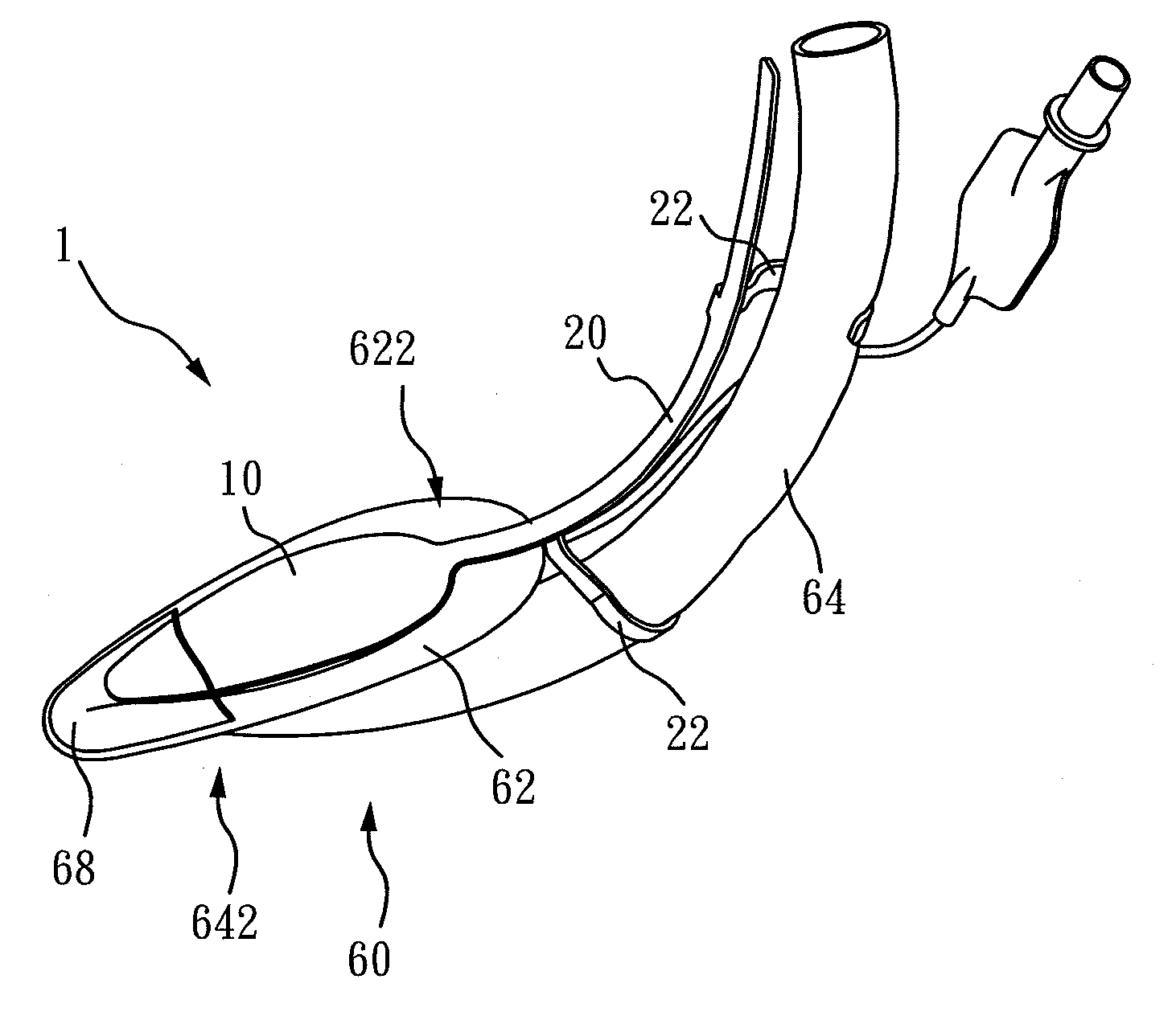
[0038]Please refer to FIG. 6, FIG. 8, FIG. 10 and FIG. 11 for explanations of the LMA of the present invention. The LMAs 60, 60a, 60b, 60c comprise a gas filled portion 62, a tube portion 64 and protection covers 68, 68a, 68b, 68c. The protection covers 68, 68a, 68b, 68c are connected to the gas filled portion 62, and the shapes and sizes of the protection covers 68, 68a, 68b, 68c are slightly different. The tube portion 64 comprises a first end 642 and a second end 644. The gas filled portion 62 is connected to the first end 642 of the tube portion 64. The gas fi...

fourth embodiment

[0044]Please refer to FIG. 11 for an illustration of the clip device installed on the LMA of the present invention. The LMA 60c comprises a gas filled portion 62, a tube portion 64, and a protection cover 68c. The clip device 1c comprises a main portion 10c and a handle portion 20c. In this embodiment, the shape of the clip device 1c matches that of the tube portion 64, such that the clip device 1c can press the tube portion 64. When the clip device 1c presses the tube portion 64, at least part of the main portion 10c is placed in the protection cover 68c.

fifth embodiment

[0045]Please refer to FIG. 12 for an illustration of the clip device installed on the LMA of the present invention. The major difference between this and the above embodiments is that the clip device 1 d comprises an image-capturing unit 82, a display unit 84 and a signal emission unit 86. The image-capturing unit 82 is used for capturing an image from a patient's upper airway. The captured image may then be directly shown on the display unit 84 connected to the handle portion 20, such that the user can determine the position of the LMA in the patient's upper airway. In addition, the image captured by the image-capturing unit 82, depending on the user's need, could be transmitted to an external display (not shown in figures) via the signal emission unit 86. Therefore, the clip device 1e of the present invention not only provides a function of facilitating the user to clip the LMA 60 but also allows the user to conveniently observe the installation status, so as to be provided with a...


PUM


Abstract

The clip device of the invention is used for clipping a laryngeal mask airway. The laryngeal mask airway comprises a gas filled portion and a tube portion. The clip device comprises a main portion and a handle portion, wherein the main portion can connect to the laryngeal mask airway. The handle portion is connected to the main portion, and the handle portion is long and thin in shape.

Description

BACKGROUND OF THE INVENTION[0001]1. Field of the Invention[0002]The present invention relates to a medical instrument; more particularly, the present invention relates to a clip device for clipping a laryngeal mask airway.[0003]2. Description of the Related Art[0004]In the case of anaesthesia or apnea patients, the top priority is the provision of pulmonary ventilation by emergency medical personnel. Among the various respiration sustaining instruments, the laryngeal mask airway (LMA), due to its ease of operability, is a common alternative to endotracheal intubation.[0005]Please refer to FIG. 1 for the structure of a conventional LMA 10P; basically, the LMA 10P mainly comprises a flexible tubular portion 11P, an inflatable sealing cuff 13P, and an inflation tube 15P, wherein the flexible tubular portion 11P comprises a first opening part 111P and a second opening part 112P, the inflatable sealing cuff 13P is disposed surrounding the first opening part 111P, and the inflation tube 1...

Claims


Application Information

Patent Timeline
Patent Type & Authority Applications(United States)
IPC IPC(8): A61M16/06
CPCA61M16/0434A61M16/0409A61M16/0488
Inventor CHEN, TIEN-SHENGYUAN, HUI-BIH
Owner CHEN TIEN SHENG
Why Eureka
Try Eureka