Power tool housing support structures

a technology for power tools and supporting structures, applied in the field of power tools, can solve problems such as cracking of tools

Active Publication Date: 2009-08-06
INGERSOLL RAND IND U S INC
View PDF14 Cites 50 Cited by
  • Summary
  • Abstract
  • Description
  • Claims
  • Application Information

AI Technical Summary

Problems solved by technology

Such tools have been known to experience cracking, particularly when dropped.

Method used


Image

  • Power tool housing support structures
  • Power tool housing support structures
  • Power tool housing support structures

Examples


Embodiment Construction

[0022]Although the invention is illustrated and described herein with reference to specific embodiments, the invention is not intended to be limited to the details shown. Rather, various modifications may be made in the details within the scope and range of equivalents of the claims and without departing from the invention.

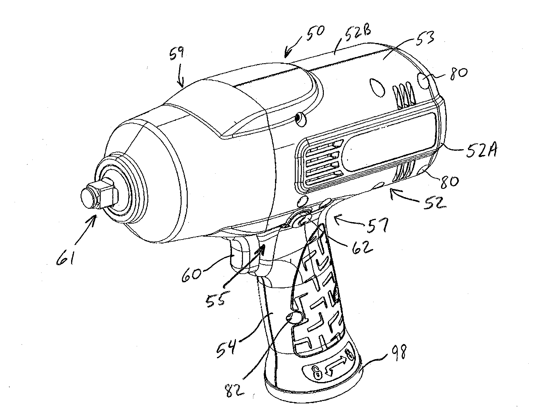
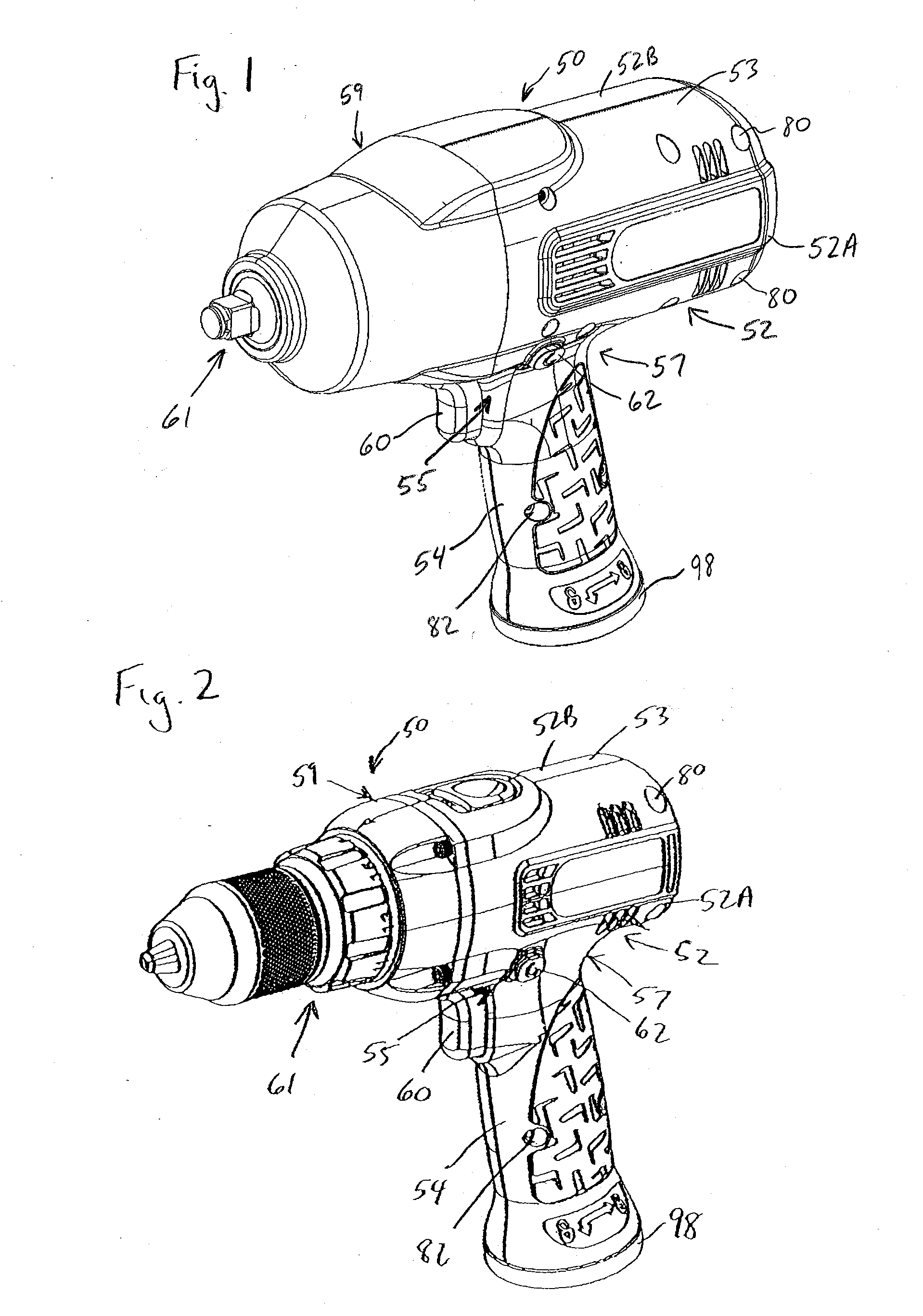
[0023]Referring to FIGS. 1-2, various exemplary power tools 50 are illustrated. In FIG. 1, the illustrated tool 50 is a cordless impact wrench and in FIG. 2, the illustrated tool 50 is a cordless drill, however, the present invention is not limited to such tools. For example, but not limited to, the tool 50 may be cordless or corded, pneumatic, or otherwise powered. Furthermore, the invention is not limited to drills and impact wrenches, but includes other power tools. Each of these illustrated tools 50 includes a tool body 52 defining a head portion 53 and a handle 54 depending therefrom. In each of these illustrated tools 50, a forward junction 55 and a rearward...


PUM

PropertyMeasurementUnit
perimetersaaaaaaaaaa
perimeteraaaaaaaaaa
areaaaaaaaaaaa

Abstract

A tool housing which in one aspect includes a body defining a head portion with a handle portion depending therefrom to define a forward and / or a rear junction. A metal reinforcing member is configured to span along an inside surface of the body from the head portion to the handle portion such that the reinforcing member bridges either the forward or rear junction. In another aspect, the tool assembly comprises a tool housing body, a motor positioned within the tool body housing, a drive mechanism connected with the motor to define a unitary motor / drive mechanism assembly, and at least one elastic isolating member extending about a portion of the motor / drive mechanism assembly such that the motor / drive mechanism assembly is elastically isolated relative to the housing body.

Description

BACKGROUND OF THE INVENTION[0001]The present invention relates to power tools, and more particularly, to tool housings for power tools.[0002]Various power tools, including corded electric, cordless electric and pneumatic tools, are well-known. Examples of such tools include, but are not limited to, drills, drill drivers, impact wrenches, grease guns and the like. Many of these tools have a pistol style housing generally including a tool body defining a head portion with a handle depending therefrom. A trigger or the like is typically provided at the forward junction of the head portion and the handle. In an effort to make such tools lighter, the tool body is typically manufactured from plastic or the like formed in a clam shell manner in which opposed halves of the body are formed separately and then joined together. Such tools have been known to experience cracking, particularly when dropped. It is also desirable to protect internal components, e.g. the motor or the like, if the to...

Claims


Application Information

Patent Timeline
Patent Type & Authority Applications(United States)
IPC IPC(8): B25F5/02
CPCB25F5/02B25F5/006
Inventor JOHNSON, JOSHUA ODELLAMEND, RYAN SCOTTBOUBOULIS, JOSEPH CONSTANTINELIVINGSTON, PATRICK SEANSOULS, DOUGLAS EDWARD
Owner INGERSOLL RAND IND U S INC
Why Eureka
Try Eureka