Cable reel trailer

a technology for cable reels and trailers, which is applied in the direction of loading/unloading vehicles, transportation items, and refuse collection, etc., can solve the problems of heavy weight of cable reels, large quantity of cables to be produced, stored and transported, and unstable cables

Inactive Publication Date: 2009-08-06
REELSTRONG
View PDF10 Cites 27 Cited by
  • Summary
  • Abstract
  • Description
  • Claims
  • Application Information

AI Technical Summary

Benefits of technology

[0010]The base includes a frame comprising two substantially parallel beams connected by at least one substantially perpendicular crossbeam. The base also includes two towers extending outwardly from the frame. The base includes two wheels. The wheels are connected to the frame or to the towers. The base also includes one or more tow beams connected to the frame, and a coupling connected to at least one of the tow beams.
[0011]The cantilevers pivot with respect to the base, thereby changing the angle between the cantilevers and the frame. The pivoting motion of the cantilevers is powered by a pair of hydraulic cylinders. The latch assembly engages and disengages the pair of cantilevers to secure them in, or release them from, a fixed position with respect to the base. The cantilevers can be connected by one or more crosspieces. The cantilevers can also include a pair of deflection gussets.

Problems solved by technology

These systems also require large quantities of cables to be produced, stored, and transported.
Cables that are not properly stored and transported are subject to damage or destruction.
Cable-filled reels are heavy and become unstable when lifted off the ground.
The task of lifting reels to transport them, or to wind and unwind cable on them, is dangerous and labor-intensive.
Such machines are often heavy or encounter problems with stability.
Flat bed trucks present the problem of inadvertent disengagement of the reel from the bed and damage to the reel.
Flatbed trucks are bulky, and cable cannot be accessed once a reel is loaded onto a bed.
Such methods are prone to accidents and create a risk of damage to reels and injury to workers.
Self-loading reel lifts and trailers known in the art do not completely overcome the problems associated with lifting and transporting reels on truck beds.
A shortcoming associated with known self-loading devices is complexity of design.
Animated parts and complicated movement causes wear and tear of the devices.
Large and numerous parts create excess mass.
Thus, known devices encounter problems of undesirable wear and undesirable weight.
These pins are sometimes forgotten, misplaced, or improperly inserted, creating the risk that a reel and / or a spindle will fall from trailer.
This risk poses a danger of injury or death to nearby people.
Such devices encounter problems of dangerous accidents.

Method used


Image

  • Cable reel trailer
  • Cable reel trailer
  • Cable reel trailer

Examples


Embodiment Construction

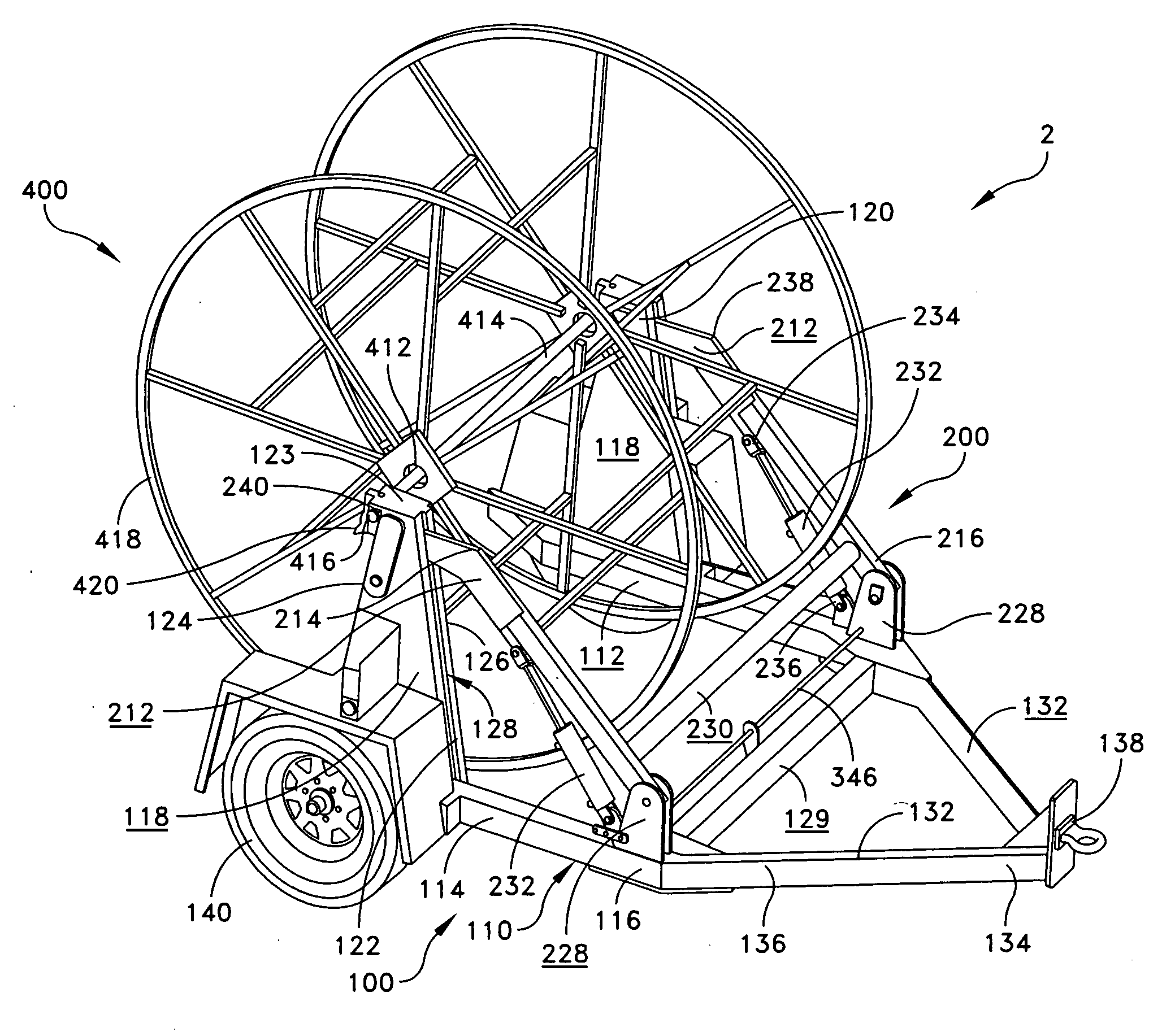
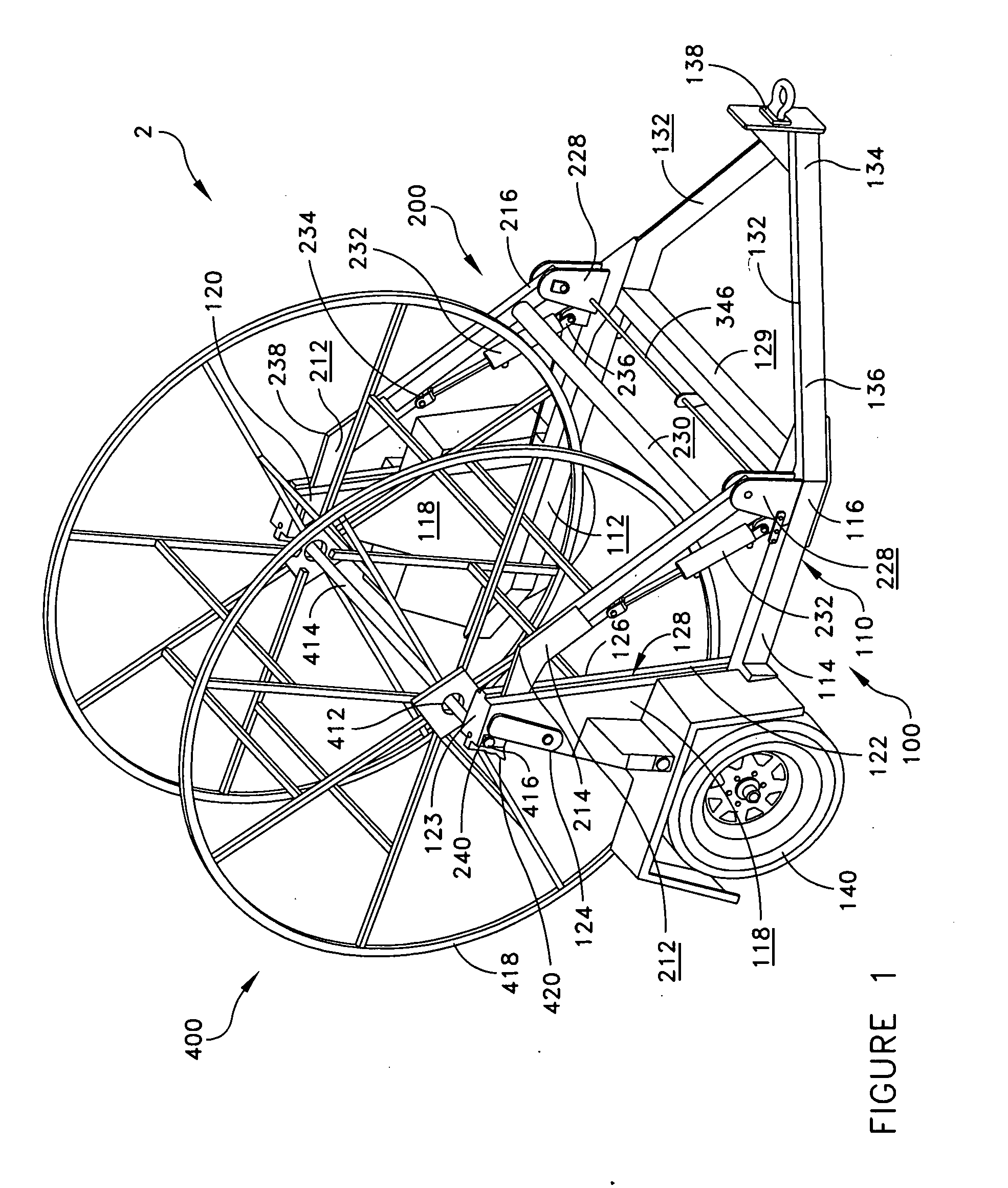
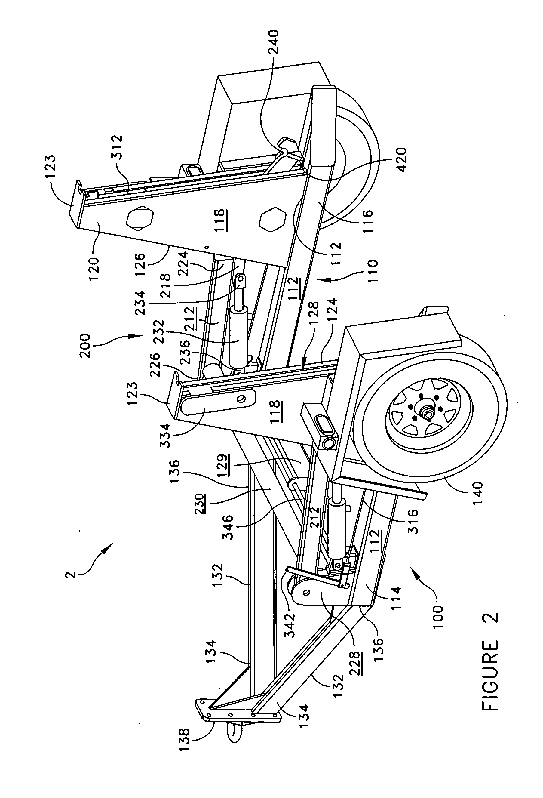
[0031]The present invention pertains to an apparatus for lifting and transporting cable reels. The description is intended to be read in connection with the accompanying drawings. The drawing figures are not necessarily to scale and certain features of the invention can be shown exaggerated in scale or in somewhat schematic form in the interest of clarity and conciseness. As used in this description, the term “proximal” refers to the end, portion, or side of a structure that is generally nearer to or generally facing the point of contact between the trailer and the reel. Likewise, the term “distal” refers to the end, portion, or side of a structure that is generally farther from or facing away from the point of contact between the trailer and the reel, as compared with that structure's proximal end, portion, or side. The terms “attached” and “connected” refer to direct attachment between structures such as by welding, riveting, or bolting, indirect attachment, such as through interv...


PUM


Abstract

The present invention pertains to a trailer for lifting and transporting cable reels. The trailer has a base, a pair of substantially perpendicular cantilevers, and a latch assembly. The cantilevers lift a cable reel off of the ground, and the latch assembly transfers at least a portion of the weight of the reel from the cantilevers to the base. The base is mounted on wheels and can be pulled or pushed by a vehicle connected to the base.

Description

[0001]This application claims priority from, and the benefit of U.S. provisional patent application Ser. No. 61 / 026,615, filed Feb. 6, 2008, entitled Cable Reel Trailer and U.S. provisional patent application Ser. No. 61 / 105,524, filed Oct. 15, 2008, entitled Cable Reel Trailer, all of which are incorporated herein by reference.FIELD OF THE INVENTION[0002]The present invention relates generally to the field of lifting and transporting equipment, and more particularly to a trailer for cable reels.BACKGROUND[0003]Electrical power, fluid power, fiber optic, and telephone systems require long extensions of cables, fibers, wires, hoses, or other elongated flexible elements (hereinafter collectively referred to as “cables”) to transmit power or information between a supply and a consumer. These systems also require large quantities of cables to be produced, stored, and transported. Cables that are not properly stored and transported are subject to damage or destruction.[0004]Cables are st...

Claims


Application Information

Patent Timeline
Patent Type & Authority Applications(United States)
IPC IPC(8): B60P1/48B65H49/38B60P1/00B60P3/035
CPCB60P3/035B65H49/38B65H49/325
Inventor SMITH, NOEL C.ZITKUS, JOHNFERGUSON, JOHNWENGER, DEANGLICK, LLOYDFORDE, BRIAN F.
Owner REELSTRONG
Why Eureka
Try Eureka