Airbag device

a technology of airbags and airbags, which is applied in the direction of textiles and papermaking, vehicle components, sewing apparatuses, etc., can solve the problems of inability to maintain the inflation of airbags, serious head injuries, and impact damage to people, so as to reduce the impact on the person and reduce the impact timely

Inactive Publication Date: 2009-08-13
MAZDA MOTOR CORP +1
View PDF19 Cites 19 Cited by
  • Summary
  • Abstract
  • Description
  • Claims
  • Application Information

AI Technical Summary

Benefits of technology

[0008]The present invention has been made to solve the above-described problem of airbag devices. Objects of the present invention are to improve the safety of airbag devices and to reduce the impact exerted on a pedestrian or the like during a secondary collision, by not releasing gas until the pedestrian or the like thrown onto the bonnet collides with the airbag, but by releasing gas at the timing of the pedestrian or the like colliding with the airbag. Another object of the present invention is to provide such airbag devices at a low cost by simplifying the structure of the airbag devices.

Problems solved by technology

The pedestrian or the like is then subjected to a secondary collision, such as going into the vehicle by breaking the windshield of the vehicle or colliding with a front pillar or the like, and may cause a disaster.
However, if a person thrown into the air collides with an inflated airbag, the person may be seriously injured by the impact.
In particular, because a person collided with a car and thrown into the air usually goes into the driver's seat side from the head, if the person pushes into the airbag during inflation, the person may receive serious injury to the head due to the resilience.
However, an airbag which simply has a vent hole allows gas to be released before absorbing impact and fails to maintain inflation of the airbag.
Thus, appropriate impact-absorbing characteristics may not be obtained in the initial stage.

Method used


Image

  • Airbag device
  • Airbag device
  • Airbag device

Examples


first embodiment

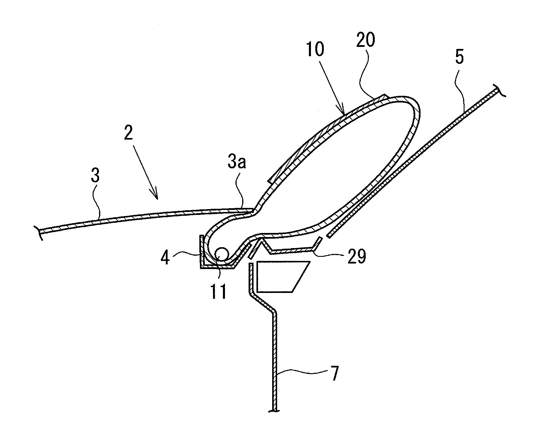
[0070]In the airbag device 1 the length of the third base fabric 20 is set shorter than the length of the front surface base fabric 14 so that tension is applied to the sewn portions 23 and 24 between the third base fabric 20 and the airbag 10, during inflation and deployment of the airbag 10. When a person hits the third base fabric 20 during collision, the internal pressure of the airbag 10 increases. This increases tension to be applied to the third base fabric 20, whereby the sewn portion 23 of the third base fabric 20 can easily and assuredly be cut.

[0071]In this structure, the cutting strength of the sewn portion 23 needs to be set in such a manner that the sewn portion 23 is not cut during high-pressure deployment of the airbag 10, but is cut, even in a low-pressure state, when a person (dummy) pushed into the airbag 10. However, providing such a sewing structure is not always easy. Further, because tension is applied to the third base fabric 20 during inflation of the airba...

third embodiment

[0084]FIG. 8 is a front view of the airbag device according to the present invention.

[0085]In the airbag device according to the third embodiment, the pillar portion 12a has both left and right side ends 40 and 41 in the figure, where a first vent hole 18A and a second vent hole 18B are formed. Both end edges (or both side portions) of the third base fabric 20 are sewn to the front and back surface base fabrics 14 and 15 at the portions of the first vent hole 18A and the second vent hole 18B, along the first sewn portion 23 and the second sewn portion 24. The vent holes 18A and 18B are sewn along the straight-line sewn portions 23a and 24a, respectively, and closed. Because the other structures are the same as those of the airbag device according to the first embodiment, the description thereof will be omitted.

[0086]In the present embodiment, for example, if the head of a person pushes into the sewn portion 23 where the third base fabric 20 and the vent hole 18A are sewn together, a...

fourth embodiment

[0090]FIG. 9 shows an airbag device according to the present invention.

[0091]In the fourth embodiment, there are a rectangular pillar portion 12a and a projecting base portion 12b. A first vent hole 18A and a second vent hole 18B that are separated from each other by a certain distance are provided in an upper end 26 in the figure of the pillar portion 12a.

[0092]Two third base fabrics 20 (third base fabrics 20(1) and 20(2)) that are sewn to the first and second vent holes 18A and 18B, respectively, at one end, are provided in such a manner that they cover the pillar portion 12a and are arranged parallel to each other.

[0093]The present embodiment is used when vent holes cannot be provided in the transverse direction of the pillar portion 12a of the airbag 10.

[0094]In the fourth embodiment, the pillar portion 12a may have a single vent hole 18, for example, in the upper end 26 in the figure. Alternatively, the pillar portion 12a may have third and fourth vent holes 18C and 18D in a l...


PUM


Abstract

Intended is to always provide effective impact reduction by releasing gas at a timing of pushing into airbag.An airbag (10) has a vent hole (18) in one side end portion. One end of a third base fabric (20) is sewn to the airbag (10) through a first sewn portion (23) that closes the vent hole (18), and the other end of the third base fabric 20 is sewn to the other side end portion of the airbag (10) through a second sewn portion (24). The first sewn portion (23) has weaker binding force by sewing than the second sewn portion (24) so that the first sewn portion (23) is separated to open the vent hole (18) when tension force is applied from the third base fabric (20) to the first and second sewn portions (23) and (24).

Description

TECHNICAL FIELD[0001]The present invention relates to an airbag device, and more specifically, to an airbag device installed in a vehicle for reducing impact exerted on a person to be protected, whose motion is difficult to be determined, during collision with the vehicle.BACKGROUND ART[0002]When, for example, a running vehicle collides with a pedestrian or the like, the pedestrian or the like is thrown onto the bonnet by the impact of the collision. The pedestrian or the like is then subjected to a secondary collision, such as going into the vehicle by breaking the windshield of the vehicle or colliding with a front pillar or the like, and may cause a disaster.[0003]Various pedestrian airbag devices for absorbing and reducing the impact of such a secondary collision have been developed. It is necessary for pedestrian airbags to maintain inflation of the airbags for relatively long period of time, until objects to be protected by the airbags (pedestrians) push into the airbags.[0004...

Claims


Application Information

Patent Timeline
Patent Type & Authority Applications(United States)
IPC IPC(8): B60R21/276B60R21/2338B60R21/34B60R21/36
CPCB60R21/2338B60R2021/23382B60R21/36B60R21/239
Inventor ISHIKAWA, TOSHIHIROYAMAJI, NAOKIHASHIZUME, TOMOKISOEMOTO, KAZUHIKOMORITANI, KEISUKE
Owner MAZDA MOTOR CORP
Why Eureka
Try Eureka