Connector with aligning plate

a technology of connecting plate and aligning plate, which is applied in the direction of electrical apparatus, connection, coupling device connection, etc., can solve the problems of positional deviation and crooked electrical connecting portions of female connector male terminals, and achieve the effect of increasing the overlap amount, reducing the overlap amount, and increasing the overlap amoun

Active Publication Date: 2009-08-13
YAZAKI CORP
View PDF3 Cites 12 Cited by
  • Summary
  • Abstract
  • Description
  • Claims
  • Application Information

AI Technical Summary

Benefits of technology

[0027]Therefore, when the aligning plate is forcibly pressed toward the terminal container by a worker's hand or another connector different from the mating connector to be engaged, the arm portion of the temporarily locking hook is pulled inward into the engaging space to be flexed inwardly. Accordingly, decrease of an overlapping amount between the projection and the surface of the aligning plate is eliminated, and hence, the aligning plate is prevented from moving toward the terminal container across this projection. As the results, the aligning plate is prevented from moving toward the terminal container, unless the aligning plate is pressed with engaging action of the mating connector. In this manner, it is possible to provide the connector with the aligning plate in which the aligning plate can be reliably held at the temporarily locked position.
[0028]According to the above configurations, the dent in a concave shape is formed in the aligning plate, and the inner face of the dent is brought into contact with the contact part. Therefore, it is possible to increase the overlapping amount between the projection and the surface of the aligning plate, without increasing a thickness of the aligning plate. Moreover, it is also possible to make an inclination angle of a part of the inner face of the dent to be butted against the contact part acute with respect to a direction of the surface of the aligning plate, without increasing the thickness of the aligning plate.
[0029]According to the above configurations, the contact part is so provided as to be brought into line contact with the aligning plate, and therefore, it becomes easy to make the vector generated in the contact part directed so as to approach a center of the engaging space.
[0030]According to the above configurations, the arm portion is curved in a direction toward the center of the engaging space as it goes toward the terminal container, in a state where a pressure is not applied to the arm portion. Therefore, an inclination angle of a taper face of the projection can be made acute with respect to the direction of the surface of the aligning plate, and the vector generated in the contact part which is positioned on the taper face can be easily directed so as to approach the center of the engaging space. Moreover, when a pressure is applied to the projection, the arm portion is elastically deformed from the curved shape to a rectilinear shape, and hence, decrease of the overlapping amount between the projection and the surface of the aligning plate is eliminated.
[0031]According to the above configurations, the aligning plate includes the shearing part which has a smaller thickness than other parts of the aligning plate, and is adapted to be sheared when the aligning plate is pressed toward the terminal container with a force exceeding a limit value of stress thereof. Therefore, it is possible to prevent the temporarily locking hook from being broken, and the connector housing can be re-used, by exchanging the aligning plate which has been broken.

Problems solved by technology

The electric connecting portions of the male terminals of the female connector are likely to be crooked, because they have a shape of an elongated rod, and there is a problem that positional deviation may occur with respect to the terminals of female type (hereinafter referred to as female terminals) which are contained in the mating male connector.

Method used


Image

  • Connector with aligning plate
  • Connector with aligning plate
  • Connector with aligning plate

Examples


Embodiment Construction

[0040]Now, a connector with an aligning plate according to an embodiment of the invention will be described referring to FIGS. 1 to 4.

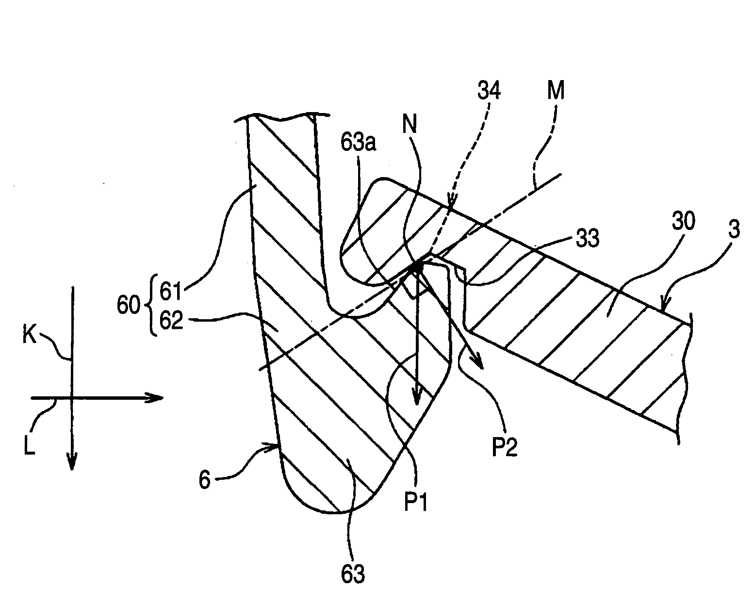
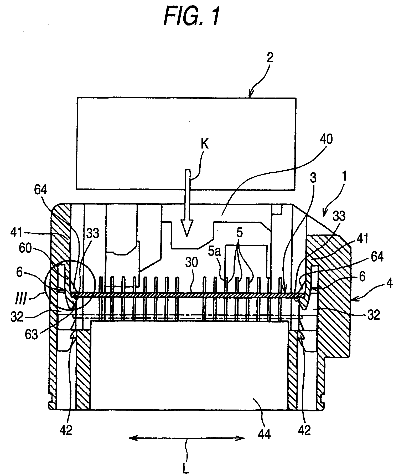
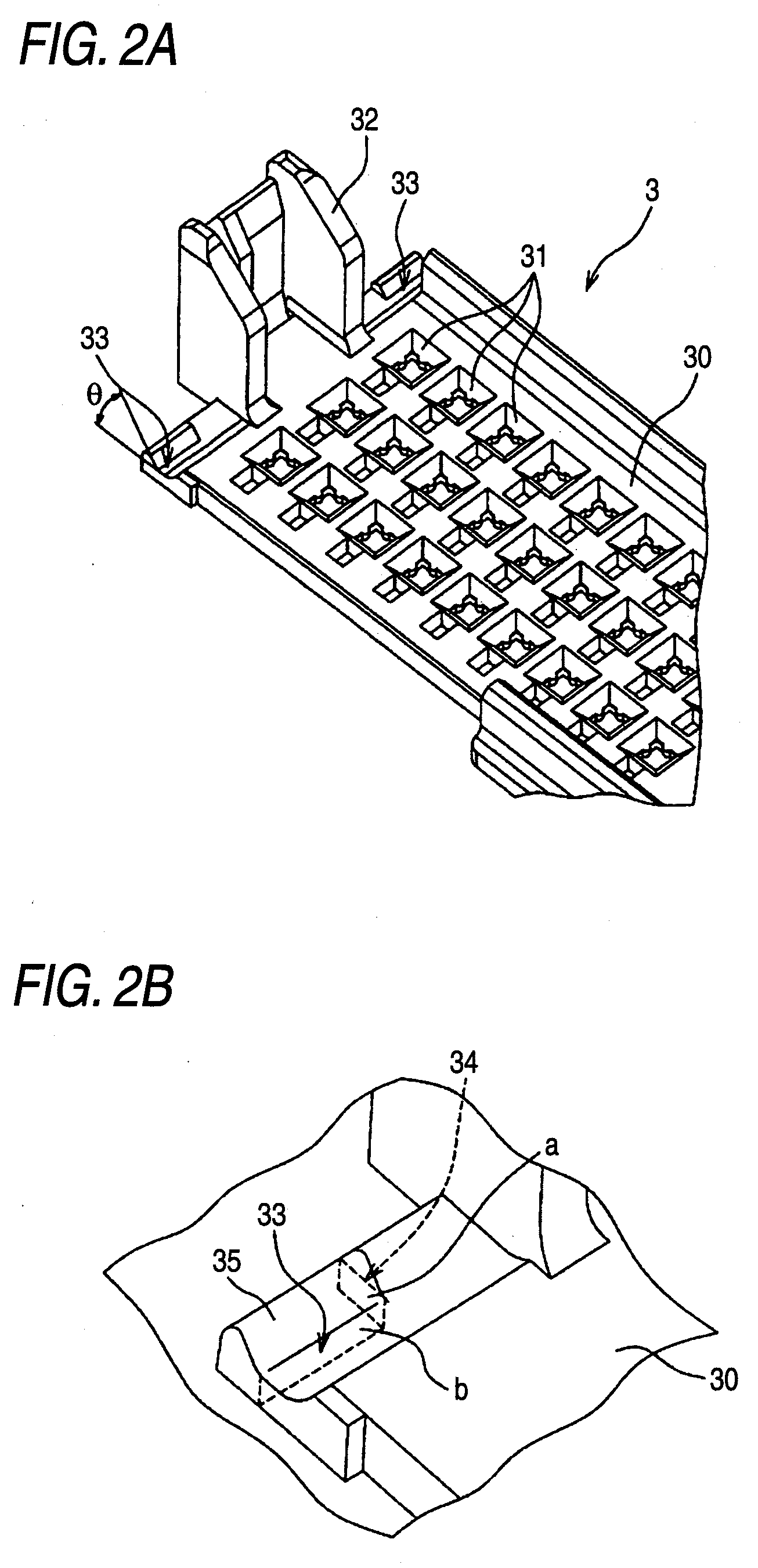
[0041]FIG. 1 is a sectional view showing a connector with an aligning plate according to an embodiment of the invention. FIG. 2A is a perspective view showing the aligning plate in the connector as shown in FIG. 1, and FIG. 2B is an enlarged perspective view showing an essential part of the aligning plate as shown in FIG. 2A. FIGS. 3A to 3D are explanatory views for explaining operation of a holding structure of the aligning plate by means of a temporarily locking hook in the connector as shown in FIG. 1, in which FIG. 3A is a view showing the aligning plate before it is held by the temporarily locking hook; FIG. 3B is a view showing the aligning plate held by the temporarily locking hook; FIG. 3C is a view showing a state where the aligning plate which is held by the temporarily locking hook is pressed; and FIG. 3D is a view showing a state where the...


PUM


Abstract

A connector, includes: a connector housing including an engaging space to receive a mating connector through the entrance, and a terminal container; a male terminal including a base end fitted to the terminal container and an electric connecting portion extended from the base end into the engaging space; an aligning plate which is arranged within the engaging space, includes a terminal insertion hole for passing the electric connecting portion therethrough, and adapted to move in the engaging space between a temporarily and a permanently locked positions; a temporarily locking hook including a projection projected from an arm portion so as to hold the aligning plate at the temporarily locked position; and a contact part provided on the projection to contact the aligning plate, so that a vector for pulling the arm portion inward into the engaging space is generated when the aligning plate is pressed toward the terminal container.

Description

BACKGROUND OF THE INVENTION[0001]1. Field of the Invention[0002]The present invention relates to a connector provided with an aligning plate for supporting male terminals and for positioning the male terminals to prescribed positions.[0003]2. Related Art[0004]As a connector for electrically connecting electric wires which are arranged in a vehicle or the like, there are a so-called male connector and a female connector. Each of the connectors includes a connector housing, and terminals which are contained in the connector housing. The aforesaid female connector includes the connector housing having an engaging space for receiving the male connector and the terminals of male type (hereinafter referred to as male terminals). Base ends of these male terminals are mounted to the terminal container of the connector housing, and electric connecting portions extended from the base ends are positioned in the engaging space.[0005]The electric connecting portions of the male terminals of the ...

Claims


Application Information

Patent Timeline
Patent Type & Authority Applications(United States)
IPC IPC(8): H01R13/627
CPCH01R13/631
Inventor MATSUMURA, KAORUTSURUTA, AKIHIROKOBAYASHI, HIROSHI
Owner YAZAKI CORP
Why Eureka
Try Eureka