Interlaminar Stabilization System

a stabilization system and interlaminar technology, applied in the field of spinal stabilization system, can solve the problems of inconvenient spinal treatment, inconvenient spinal treatment, and inconvenient implantation of pedicle screw systems, and achieve the effects of minimizing the space between the insertion profile, and reducing the insertion profil

Inactive Publication Date: 2009-08-13
PIONEER SURGICAL TECH INC
View PDF16 Cites 28 Cited by
  • Summary
  • Abstract
  • Description
  • Claims
  • Application Information

AI Technical Summary

Benefits of technology

[0009]One advantage of this form is that it allows the spinal implant assembly to have a minimal insertion profile. This is beneficial because the smaller the insertion profile, the less the adjacent vertebrae must be distracted, if at all...

Problems solved by technology

However, both hook and rod and pedicle screw systems have limitations and are not appropriate for all types of spinal disorders.
The implantation of pedicle screw systems are intricate, time consuming, and invasive into the spine of the patient.
The system of screws and rods creates an intricate system for supporting the spine that takes considerable effort.
The placement of the screws and rods is time consuming because the components mus...

Method used


Image

  • Interlaminar Stabilization System
  • Interlaminar Stabilization System
  • Interlaminar Stabilization System

Examples


Embodiment Construction

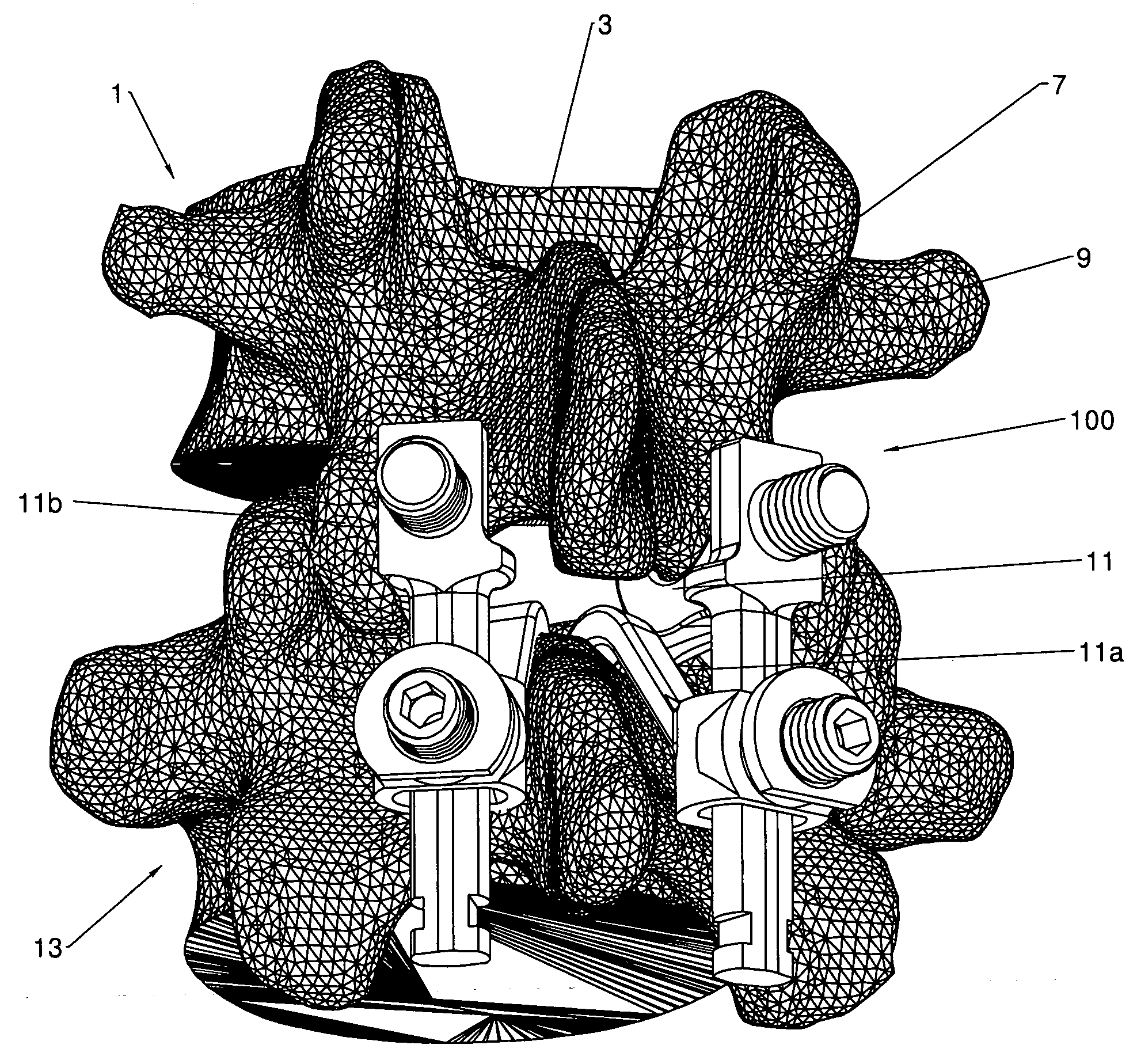
[0071]Generally, the present invention provides a spinal stabilization system for supporting at least one vertebra of a spine and, more particularly, a laminar region of at least one vertebra. Referring briefly to FIGS. 7A, 7B,15,16, a vertebra 1 of a spine generally includes a body 3 and a vertebral arch 5 defining a vertebral foramen 15. The vertebral arch 5 includes a spinous process 7, a pair of transverse processes 9, a laminar region 11, and pedicle regions 13. The spinous process 7 extends generally directly posterior to the body 3 opposite the vertebral foramen 15. The laminar region 11 is disposed directly behind the spinous process 7 and extends between and interconnects the spinous process 7 to the transverse processes 9. The transverse processes 9, therefore, extend generally laterally from the laminar region 11 on each side of the spinous process 7. The pedicle regions 13 are disposed between and interconnect the transverse processes 9 and, therefore, the entire vertebr...


PUM


Abstract

A spinal stabilization system includes vertebral engagement members and an intermediate structure. The vertebral engagement members are configured to be disposed between a first vertebra and a second vertebra. The vertebral engagement members generally include seating surfaces for accommodating at least a portion of a laminar region of adjacent vertebra and are adjustable between an operable and inoperable configuration. The intermediate structure extends between the vertebral engagement members. The structural cooperation of the vertebral engagement members and the intermediate structure is such that the engagement members distract the adjacent vertebrae.

Description

CROSS-REFERENCE TO RELATED APPLICATIONS[0001]This application claims the benefit of Provisional Application Ser. No. 60 / 973,659 filed on Sep. 19, 2007, the disclosure of which is hereby incorporated in its entirety by reference.FIELD OF THE INVENTION[0002]The present invention relates generally to a spinal stabilization system and, more particularly, a spinal stabilization system for distracting and limiting reduction of the intervertebral spacing between adjacent vertebrae.BACKGROUND OF THE INVENTION[0003]This invention pertains generally to medical implantable devices and particularly to spinal implants. Various devices for internal fixation of bone segments in the human or animal body are known in the art. The most common type of spinal implant system are hook and rod systems and pedicle screw systems which provides a means of gripping a spinal segment. However, both hook and rod and pedicle screw systems have limitations and are not appropriate for all types of spinal disorders....

Claims


Application Information

Patent Timeline
IPC IPC(8): A61B17/70
CPCA61B17/7001A61B17/7004A61B17/7008A61B17/7091A61B17/7049A61B17/7056A61B17/7079A61B17/7014
Inventor HOCHSCHULER, STEPHENARAGHI, ALISONGER, MATTHEW N.KILPELA, THOMAS S.BUTTERS, JOSHUA A.HAYS, GRETA JO
Owner PIONEER SURGICAL TECH INC
Why Eureka
Try Eureka