

Monitor for automatic resuscitator with primary and secondary gas flow control
a technology of automatic resuscitation and monitoring device, which is applied in the direction of valves, respirators, operating means/releasing devices, etc., and can solve problems such as alarm condition
Inactive Publication Date: 2009-08-20
VORTRAN MEDICAL TECH 1
View PDF17 Cites 22 Cited by
- Summary
- Abstract
- Description
- Claims
- Application Information
AI Technical Summary
Benefits of technology
[0013]In a further embodiment, the processor can utilize the clock unit to trigger flow-on and flow-off primary gas control valve conditions with a delay or advancement of time depending up the trigger event by the detection of a low pressure pulse from the automatic resuscitator. The time duration of the primary gas control valve being either on or off can also be set to be a fraction or proportion of time wherein the inhalation or flow-on condition and the exhalation or flow-off condition is determined by mathematic division of the time duration from a low pressure signal to a total allowable time, thus creating a ratio of inhalation to exhalation. By using a gas management system in accordance with the present invention, gas supply can be conserved by up to 65% over a system which does not interrupt gas flow.
Problems solved by technology
Failure of the resuscitator system itself to generate a low pressure signal against the integrated time clock causes an alarm condition.
Method used
View moreImage
Smart ImageViewing Examples

Examples
example
[0059]A monitor with gas flow control was fabricated in accordance with the present invention.
[0060]Upon testing, the device was routinely capable of maintaining operation under the following conditions:
[0061]Peak Inhalation Pressure Range: 10 to 50 cm-water
[0062]Gas Flow Rates: Up to and including 40 liters per minute
[0063]Maximum Gas Supply Pressure: 50 PSI
[0064]Operation Time under Continuous Duty: >72 hrs
Login to View More PUM
 Abstract
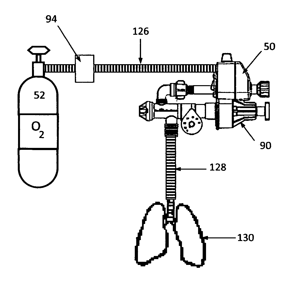
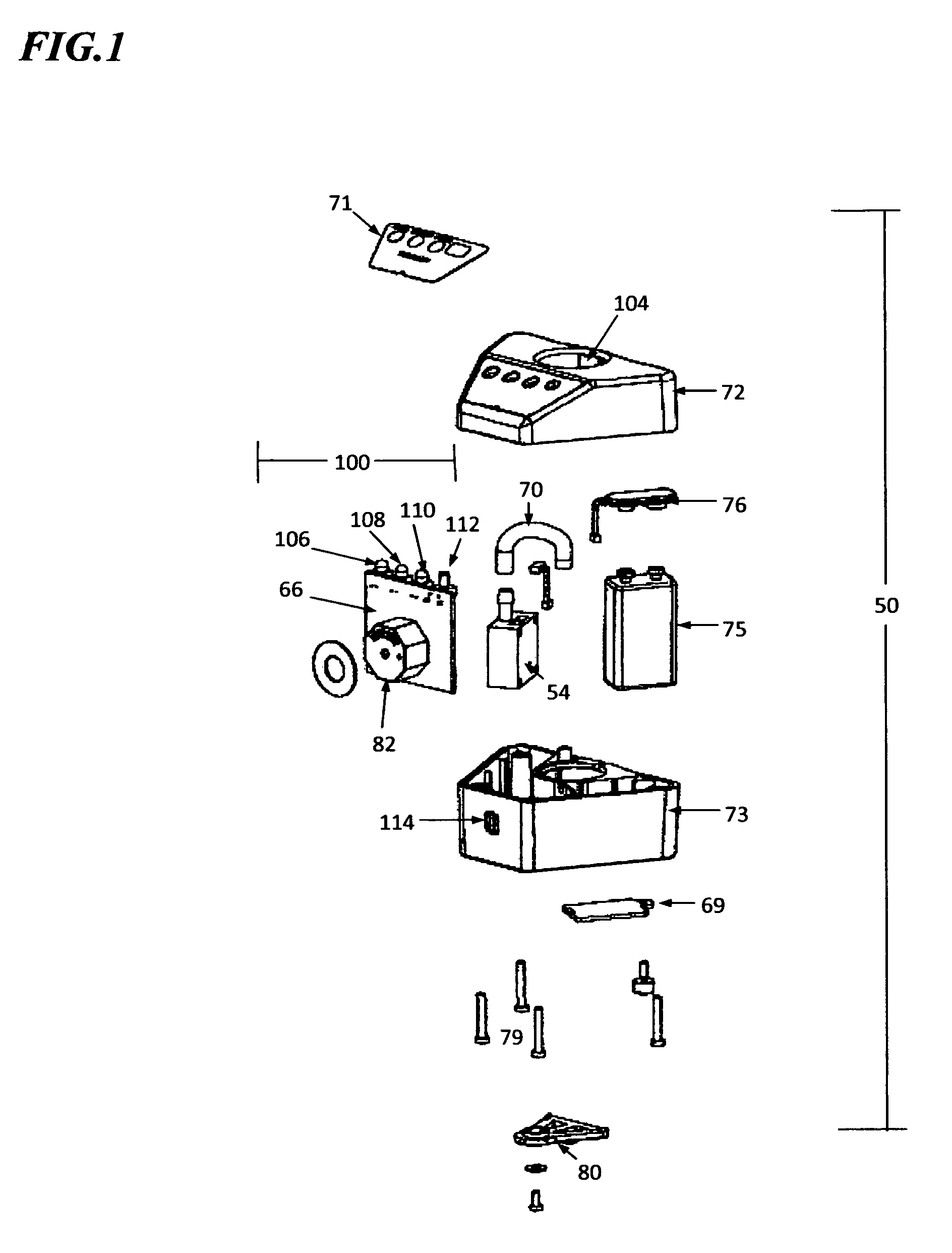
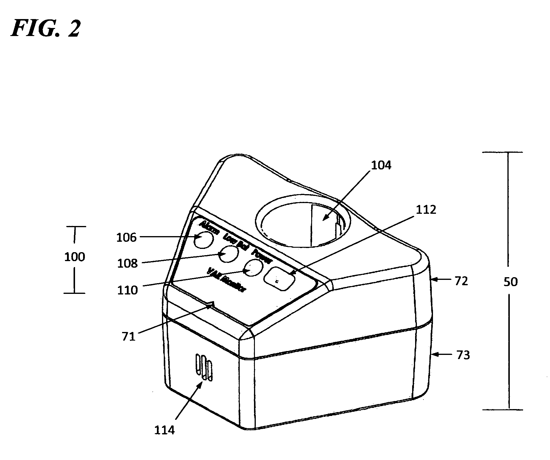
The present invention pertains generally to a monitoring system for a resuscitator which detects operation of the resuscitator and a controller unit for a supply of therapeutic gas to a resuscitator, and more specifically, a flow controller for a supply a therapeutic gas to an automatic resuscitator which is triggered by a single point pressure signal provided by the cycling of the automatic resuscitator from a controlled inhalation phase to a controlled exhalation phase. The monitoring aspect of the system detects single point low pressure signals which are sequentially compared against a time clock. Failure of the resuscitator system itself to generate a low pressure signal against the integrated time clock causes an alarm condition. Further, gas management is effected by a flow controller integrated into the monitor, a gas management system which responds to the single point low pressure signal and operate a primary gas control valve attached between a gas supply and an automatic resuscitator such that gas is allowed to flow to the resuscitator when the resuscitator is in an inhalation mode and gas flow is interrupted when the resuscitator is in an exhalation mode. A secondary gas control valve is integrated into the gas management system in parallel to the primary gas control valve. The flow controller includes a low threshold pressure sensor which is actuated by means of a recurrent low pressure pulse generated by the automatic resuscitator itself through the cycling of the resuscitator and remains essentially unaffected by the respiratory cycling of the patient, thus preventing false triggers and greatly simplifying the flow controller operation and format. The low threshold pressure sensor is coupled to a processor wherein the processor reads the occurrence of a pressure event at the pressure sensor and which then closes the primary gas control valve and starts a clock. As the pressure is decreased in the gas management system resulting from the primary gas control being moved to a closed position, the secondary gas control valve moves to open state, thus allowing the gas management system to vent to atmosphere during exhalation, reducing the pressure of the system to an operator defined positive level. Once the clock reaches a pre-defined duration, the primary gas control valve is reopened, the pressure in the gas management system increases thus closing the secondary gas control valve, the automatic resuscitator continues into an inhalation mode, and the process repeats.
Description
BACKGROUND[0001]A fundamental aspect of providing respiratory care to a patient is the ability to provide continuous ventilatory support to a patient requiring respiratory assistance. Ventilatory support is typically provided by clinicians and emergency medical personnel through the use of a manual resuscitator or a completely automatic ventilator device. Decisions as to which device to use is dependent on equipment availability and the personnel resources obtainable to operate the chosen device within necessary functional controls.[0002]Manual resuscitators are generally equipped with a self-inflating bag, a series of check valves, which control the direction of inhalation and exhalation gases, and a patient interface that is either of a nature to fit closely about the patient's nose and mouth or in the alternative, has a port for connecting to an endotracheal tube. Such manual type resuscitators are preferentially connected to a continuous supply of therapeutic gas containing a kn...
Claims
Login to View More Application Information
Patent Timeline
 IPC IPC(8): A61M16/00
CPCA61M16/00A61M16/0051A61M16/20A61M2016/0027A61M2016/0039A61M2202/0208A61M16/209A61M2205/581A61M2205/583A61M2205/8206A61M2209/082A61M16/202A61M2205/18A61M16/0858A61M16/204A61M16/024
InventorTHOMSON, GLENLEE, JAMES I-CHESAIED, ABDOLREZA
OwnerVORTRAN MEDICAL TECH 1