
Systems and methods for extended volume range ventilation

a technology of extended volume range and ventilation system, which is applied in the field of ventilation system, can solve the problems of poor accuracy of gas mixture comprising air with twenty-two percent oxygen content to be delivered to neonatal patients, high cost of pre-mixed gases, inflexible and inconvenient,

Inactive Publication Date: 2009-08-20
TYCO HEALTHCARE GRP LP
View PDF107 Cites 172 Cited by
  • Summary
  • Abstract
  • Description
  • Claims
  • Application Information

AI Technical Summary

Benefits of technology

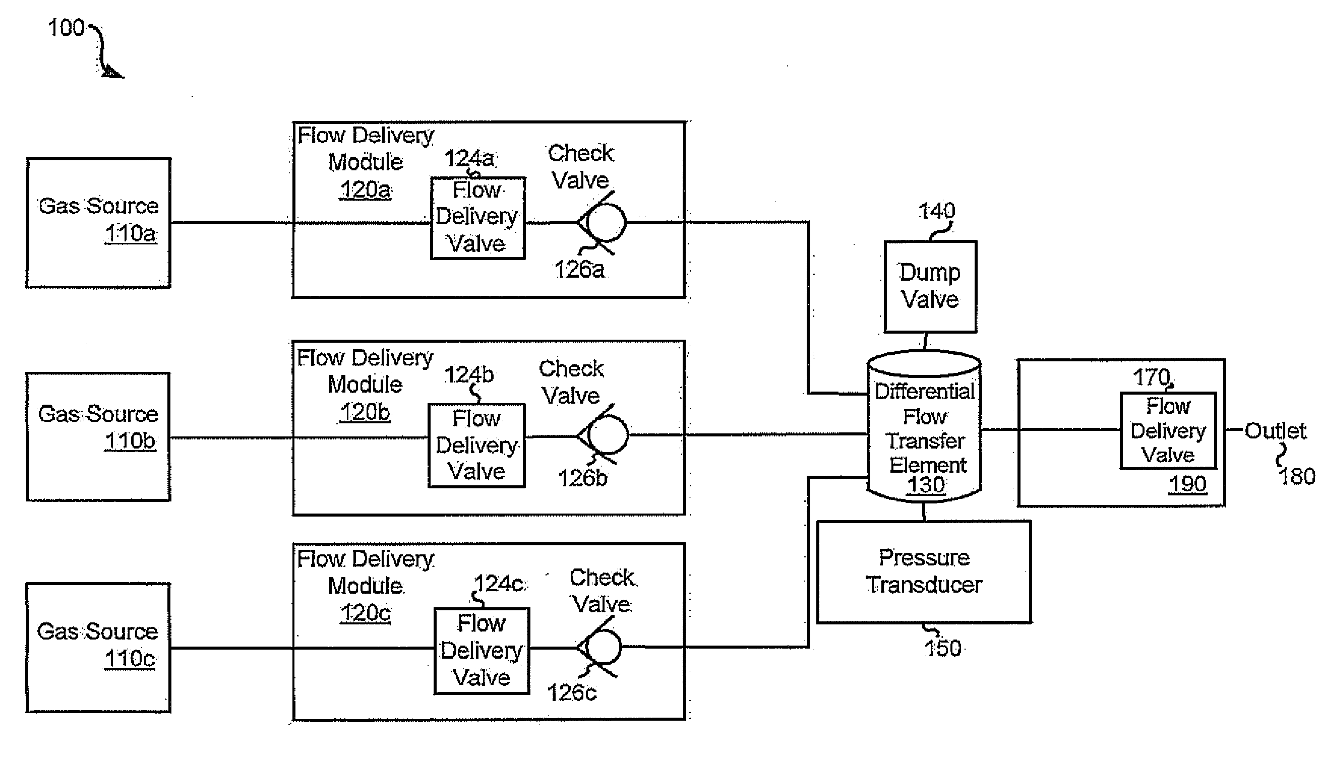
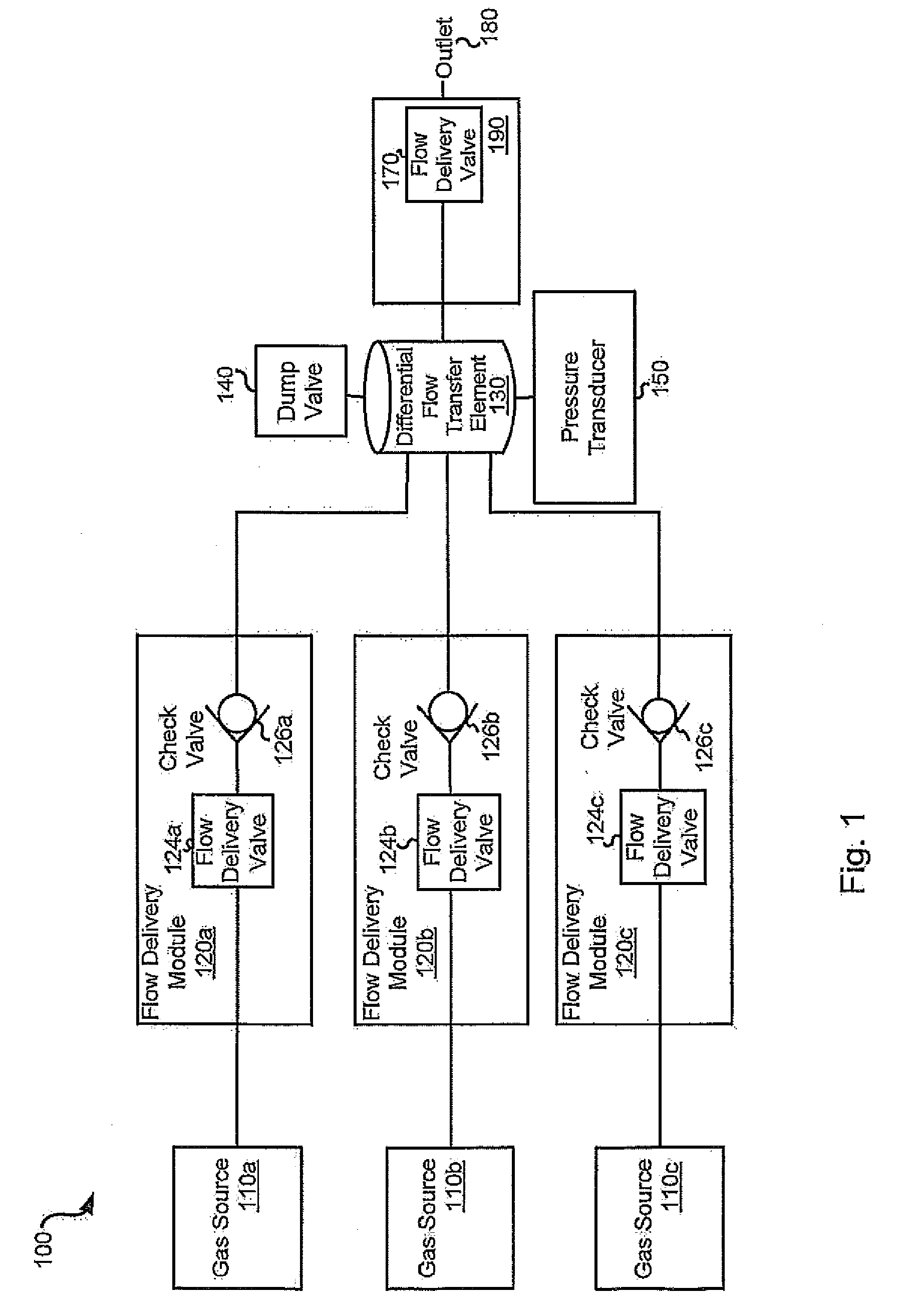
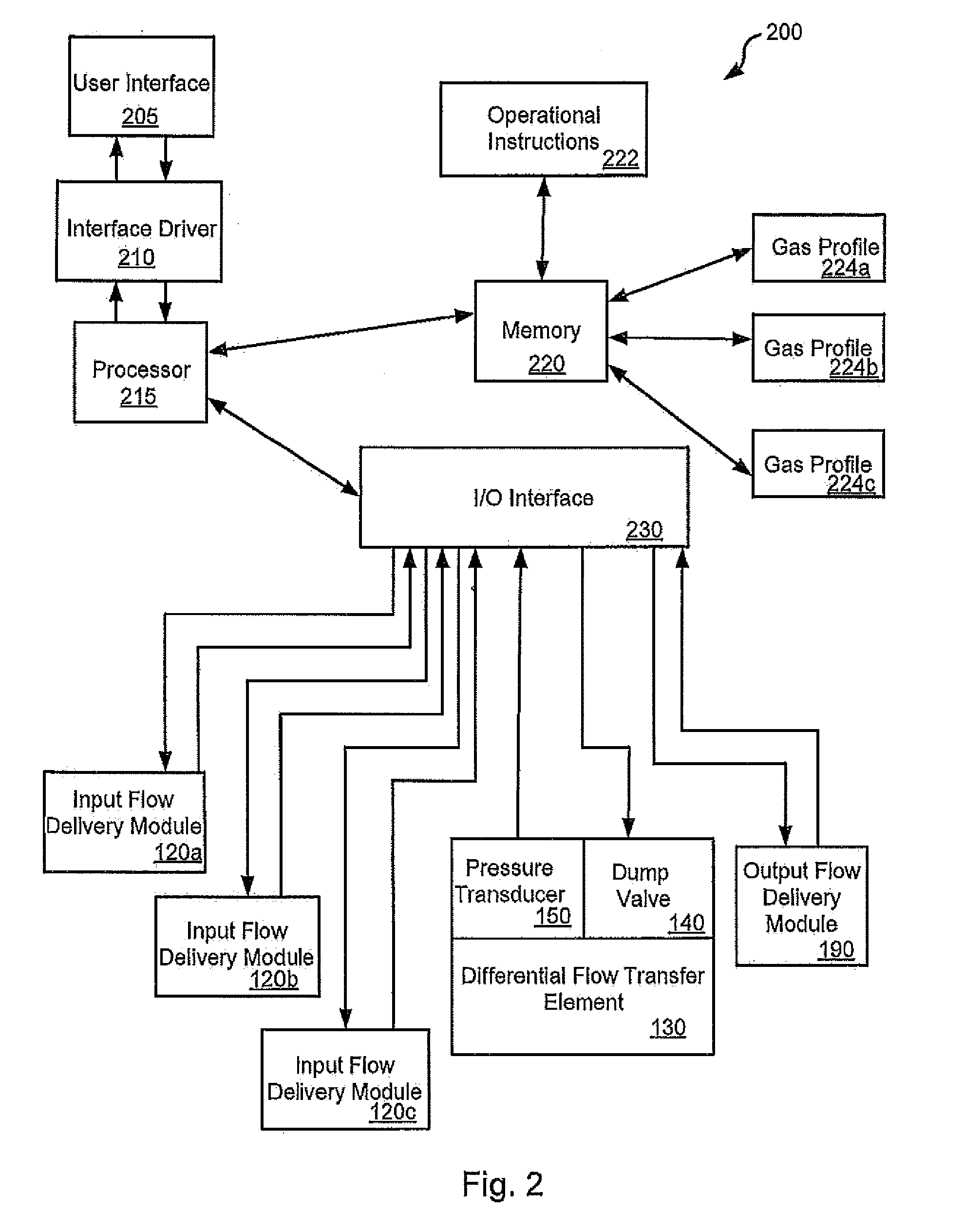
The present invention relates to ventilators that can mix gases in a controlled manner. The invention includes a differential flow transfer element that receives gases from two sources and distributes them to an outlet. The gases are mixed at a flow rate that is less than the sum of the flow rates of the two sources. The invention also includes a computer system that receives a request for a specific mixture of gases and calculates the flow rates of the gases needed to achieve the desired mixture. The technical effects of the invention include the ability to control the mixing of gases in a ventilator, which can improve respiratory therapy for patients with breathing disorders.

Problems solved by technology

Such a process aids a patient in their inspiratory efforts; however, it requires pre-mixed gases that can be expensive, inflexible and inconvenient.
In such ventilators, the accuracy of the gas content and volume provided to a patient is limited by the accuracy of each of the flow delivery valves.
In contrast, the accuracy of a gas mixture comprising air with a twenty-two percent oxygen content to be delivered to a neonatal patient may be poor due to the insubstantial amount of oxygen combined with the air.

Method used


Image

  • Systems and methods for extended volume range ventilation
  • Systems and methods for extended volume range ventilation
  • Systems and methods for extended volume range ventilation

Examples


Embodiment Construction

[0020]The present invention is related to ventilators, and more particularly to systems and methods for mixing gases in a ventilator.

[0021]Various embodiments of the present invention provide ventilators that are capable of receiving one or more component gases at programmed flow rates to yield a desired gas mixture, and for distributing the gas mixture at an output flow rate. The input flow rate is the sum of the flow rates for the component gases introduced to the ventilator, and is not necessarily the same as the output flow rate. Particular embodiments of the present invention exhibit an output flow rate that is substantially less than the combined input flow rate for a given time period. Thus, as one example, the input flow rate may be sustained for thirty seconds and then paused for three minutes at the same time that the output flow rate is consistently producing the gas mixture to a recipient at a flow and periodicity consistent with human breathing patterns. In various inst...


PUM

PropertyMeasurementUnit
pressureaaaaaaaaaa
flow rateaaaaaaaaaa
volumeaaaaaaaaaa

Abstract

Various embodiments of the present invention provide systems, methods and devices for delivering a defined gas mixture to a recipient. For example, various embodiments of the present invention provide ventilators that include at least two gas sources, a gas outlet and a differential flow transfer element. The differential flow transfer element receives one component gas from one of the gas sources at a first flow rate, and another component gas from the other gas source at a second flow rate. The differential flow transfer element distributes a mixture that includes at least the aforementioned component gases at a third flow rate via the gas outlet. The third flow rate is less than the sum of the first flow rate and the second flow rate.

Description

RELATED APPLICATION[0001]This application claims priority from U.S. Patent Application No.61 / 030,103 which was filed on Feb. 20, 2008, and is incorporated herein by reference in its entirety.BACKGROUND OF THE INVENTION[0002]The present invention is related to ventilators, and more particularly to systems and methods for mixing gases in a ventilator.[0003]Modern ventilators are designed to ventilate a patient's lungs with gas, and to thereby assist the patient when the patient's ability to breathe on their own is somehow impaired. In a simple situation, a ventilator receives a defined gas mixture at a constant rate, and provides the defined gas mixture to the patient at the same constant rate. Such a process aids a patient in their inspiratory efforts; however, it requires pre-mixed gases that can be expensive, inflexible and inconvenient.[0004]More sophisticated ventilators provide for mixing gases from different gas sources to yield a desired gas mixture for a patient. In particula...

Claims


Application Information

Patent Timeline
Patent Type & Authority Applications(United States)
IPC IPC(8): A61M16/12A61M16/20B01F23/10
CPCA61M16/0051A61M16/12A61M16/208A61M2202/0208A61M16/204A61M2202/0266A61M2205/3331A61M2205/50A61M16/203A61M2202/025A61M16/024
Inventor STEPHENSON, ROBERTGUY, JONSANCHEZ, GABRIELWINTER, DAVID P.
Owner TYCO HEALTHCARE GRP LP
Learn More