Isothermal vapor chamber and support structure thereof

Inactive Publication Date: 2009-08-20
CELSIA TECH TAIWAN INC
View PDF10 Cites 14 Cited by
  • Summary
  • Abstract
  • Description
  • Claims
  • Application Information

AI Technical Summary

Benefits of technology

[0010]It is a primary objective of the present invention to overcome the foregoing shortcomings by providing an isothermal vapor chamber and its support structure, wherein partition channels are designed among a plurality of wavy plates of the support structure for enhancing the heat conducting efficiency of the isothermal vapor chamber.
[0011]Another objective of the present invention is to provide a support structure of an isothermal vapor chamber, such that the module design of the support structure capable of fitting different models of isothermal vapor chambers is provided for lowering the manufacturing cost.
[0012]A further objective of the present invention is to provide a support structure of an isothermal vapor chamber, wherein the wave peak sections of any two adjacent wavy plates are installed alternately, such that the isothermal vapor chamber is exerted evenly by a force to prevent the isothermal vapor chamber from being collapsed or deformed.
[0015]Compared with the prior art, the support structure of the present invention is installed and partitioned by the wavy plates to form the partition channels and overcome the shortcoming of a poor heat conducting efficiency of the partition channels due to the long path of the isothermal vapor chamber. Therefore, the present invention can achieve the effect of enhancing the heat conducting efficiency.

Problems solved by technology

As the computing speed of CPU in a computer becomes increasingly higher, the heat generated by the CPU also increases accordingly, and thus a general heat dissipating device composed of aluminum extrusion heat sink and fan no longer satisfies the requirements for the CPU anymore, and manufacturers keep on developing heat pipes and isothermal vapor chambers with a higher heat conducting performance, and combining the heat pipes and isothermal vapor chambers with heat sinks to overcome the heat dissipation issue effectively.
Since the path of heat dissipating is very long, therefore the heat conducting efficiency of the isothermal vapor chamber becomes poor and adversely affects the performance of dissipating heat from the heat generating component.

Method used


Image

  • Isothermal vapor chamber and support structure thereof
  • Isothermal vapor chamber and support structure thereof
  • Isothermal vapor chamber and support structure thereof

Examples


Embodiment Construction

[0024]The technical characteristics, features and advantages of the present invention will become apparent in the following detailed description of the preferred embodiments with reference to the accompanying drawings. It is noteworthy to point out that the preferred embodiments are used for illustrating the present invention only, but not intended to limit the scope of the present invention.

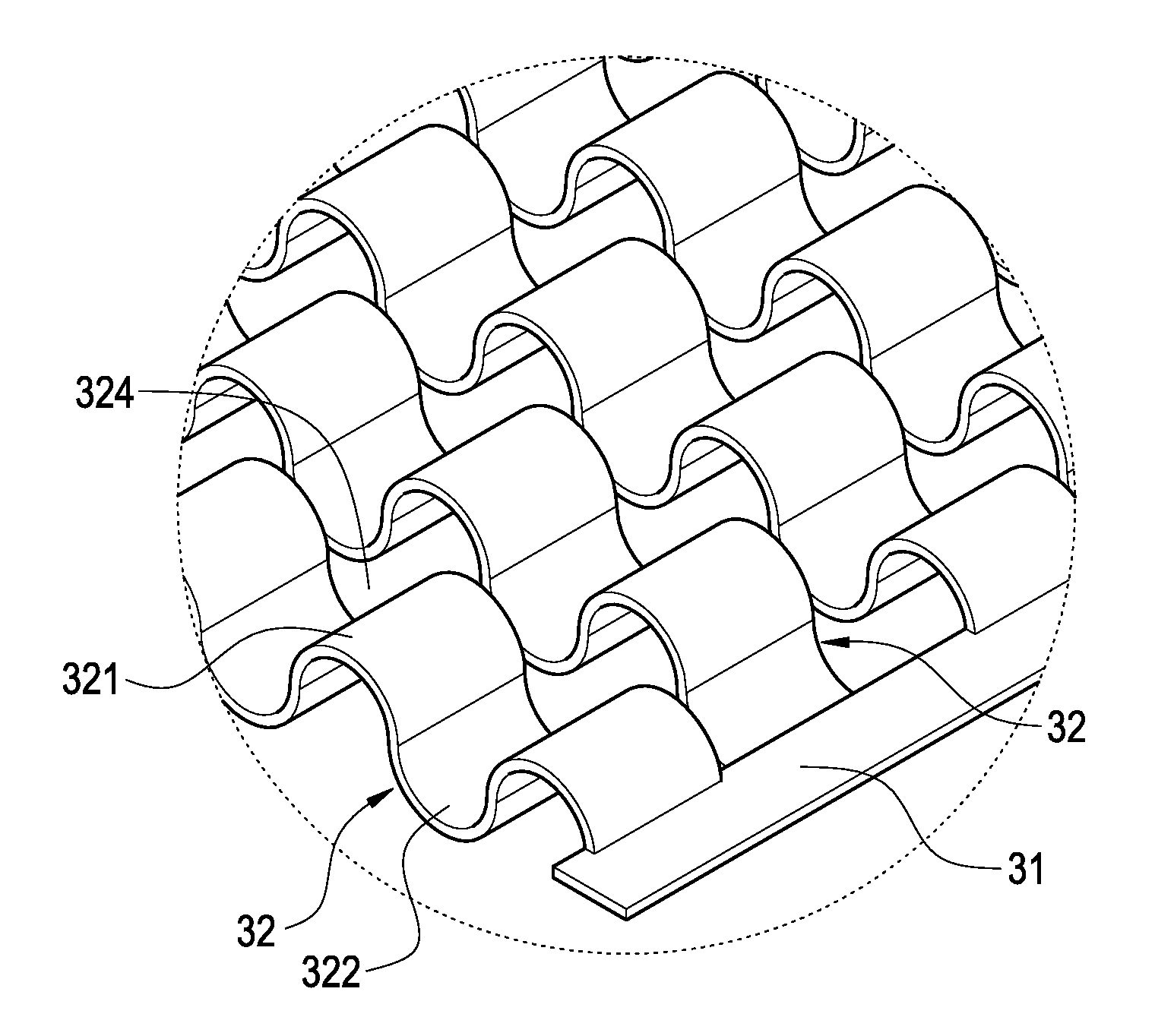
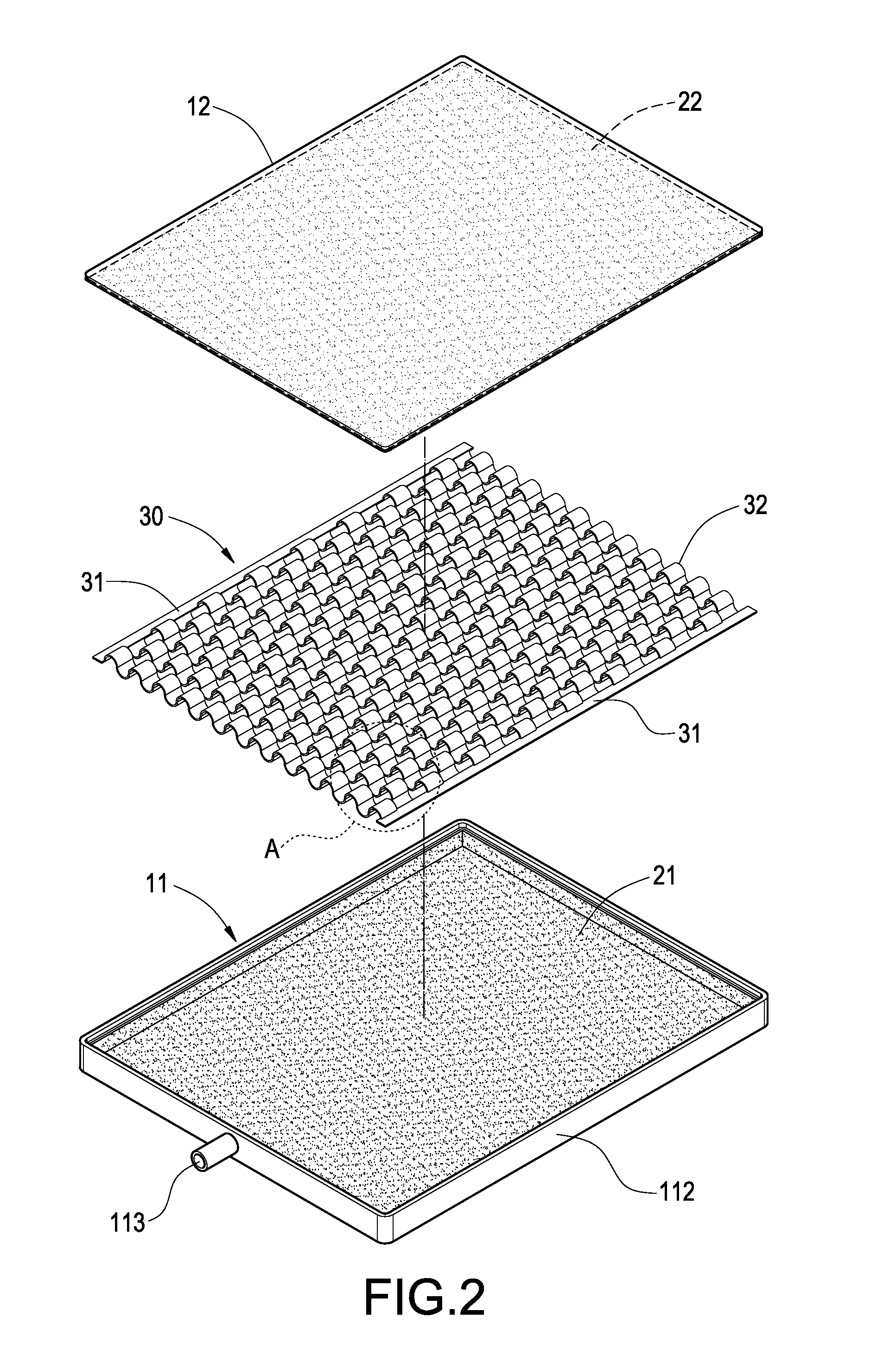
[0025]Referring to FIGS. 2 to 5, the isothermal vapor chamber of the invention is formed by a casing 10, a capillary wick 20, a support structure 30, and a working fluid 40.

[0026]The casing 10 comprises a lower casing panel 11 and an upper casing panel 12 sealed and coupled to the lower casing panel 11, and the lower casing panel 11 is formed by a bottom panel 111 and a plurality of surrounding panels 112 disposed around the periphery of the bottom panel 111, wherein the surrounding panel 112 installs a filling pipe 113 connected both to the interior and exterior of the casing 10.

[0027]The capil...


PUM


Abstract

In an isothermal vapor chamber and its support structure, the isothermal vapor chamber includes a casing, a capillary wick, a support structure and a working fluid. The capillary wick is disposed in the casing. The support structure is contained in the capillary wick for supporting the capillary wick and the support structure includes two side panels and a plurality of wavy plates are connected between the two side panels. The wavy plate is formed by a plurality of wave peak sections and a plurality of wave valley sections, and the wave peak sections of any two adjacent wavy plates are installed alternately with each other, and any two adjacent wavy plates are partitioned to form a partition channel. The working fluid is filled into the casing and flowed through the partition channel for improving the heat conducting efficiency of the isothermal vapor chamber.

Description

BACKGROUND OF THE INVENTION[0001]1. Field of the Invention[0002]The present invention generally relates to a support structure, and more particularly to a support structure of an isothermal vapor chamber and the isothermal vapor chamber.[0003]2. Description of Prior Art[0004]As the computing speed of CPU in a computer becomes increasingly higher, the heat generated by the CPU also increases accordingly, and thus a general heat dissipating device composed of aluminum extrusion heat sink and fan no longer satisfies the requirements for the CPU anymore, and manufacturers keep on developing heat pipes and isothermal vapor chambers with a higher heat conducting performance, and combining the heat pipes and isothermal vapor chambers with heat sinks to overcome the heat dissipation issue effectively. Since the isothermal vapor chamber provides a direct large-area contact with a heat generating component, it attracts more manufactures to put in their efforts on the research of isothermal va...

Claims


Application Information

Patent Timeline
IPC IPC(8): F28D15/00
CPCF28D15/046F28D15/0233
Inventor MEYER, IV, GEORGE ANTHONYLU, YUNG-TAISUN, CHIEN-HUNGHSIEH, MING-KUEILEE, I-YING
Owner CELSIA TECH TAIWAN INC
Why Eureka
Try Eureka