Communication System for a Radio-Frequency Load Control System

a communication system and radio frequency technology, applied in the field of load control systems, can solve the problems of long time (900 msec) between the original digital message and the original digital message, and the intensity of the lighting load is over- or under-determined

Inactive Publication Date: 2009-08-20
LUTRON TECH CO LLC
View PDF63 Cites 294 Cited by
  • Summary
  • Abstract
  • Description
  • Claims
  • Application Information

AI Technical Summary

Benefits of technology

[0011]According to the present invention, a method of transmitting a digital message across a communication network having a plurality of control devices comprising the steps of: (1) transmitting a first digital message; (2) propagating the first digital message through the communication network; (3) determining that a second digital message has a higher priority th

Problems solved by technology

The load control devices and master controls of the RF lighting control system of the '442 patent have limited communication ranges.
Since the load control devices and the master controls of the RF lighting control system wait until the propagation of a transmitted digital message is complete before transmitting a new digital message, there can be a substantially long time (i.e., 900 msec) between when the original digital message and the new digital message may be transmitted.
This delay between transmissions can cause a number of problems when the control devices of the RF lighting control system are physically spaced apart in a large area and the system includes a large number of signal repeaters (e.g., five signal repeaters).
For example, when a master control having raise and lower buttons is controlling a load control device and is located a lon

Method used


Image

  • Communication System for a Radio-Frequency Load Control System
  • Communication System for a Radio-Frequency Load Control System
  • Communication System for a Radio-Frequency Load Control System

Examples


first embodiment

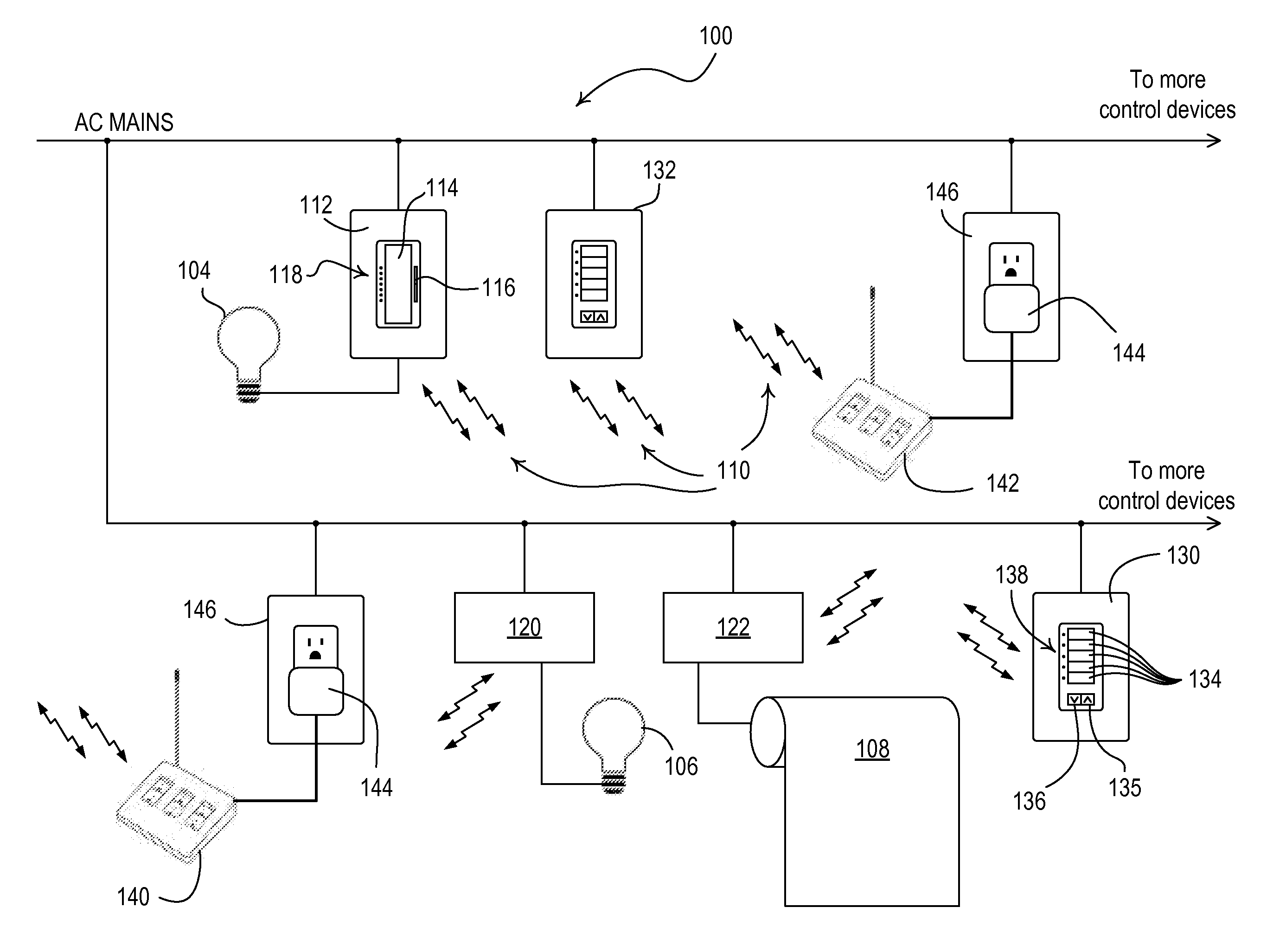
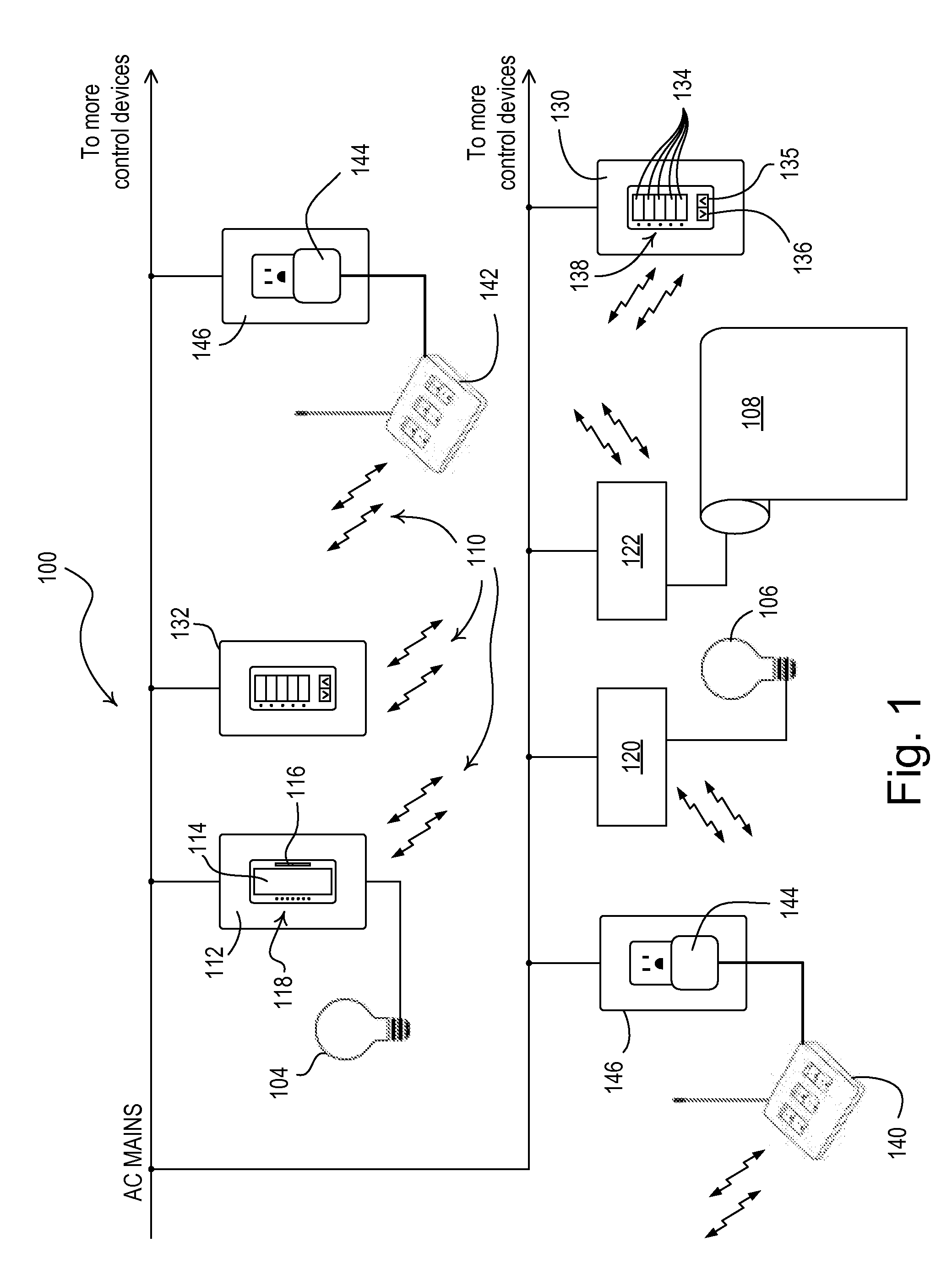
[0034]FIG. 1 is a simplified block diagram of an RF load control system 100 according to the present invention. The RF load control system 100 is operable to control the power delivered from a source of AC power (e.g., an AC mains voltage, such as 120 VAC @60 Hz) to a plurality of electrical loads, for example, lighting loads 104, 106 and a motorized roller shade 108. The RF load control system 100 utilizes a wireless RF communication link for communication of digital messages between the control devices of the system via wireless RF signals 110. Each of the control devices is assigned an address (i.e., a unique identifier) during configuration of the load control system 100 to allow each of the control devices to transmit the digital message to a specific control device. According to the present invention, the control devices of the load control system 100 communicate the digital messages using a time division technique, i.e., each control device transmits digital message during pr...

second embodiment

[0095]FIG. 13 is a simplified flowchart of a receiving procedure 1000 executed by a control device of a mesh network according to the present invention. The receiving procedure 1000 allows the control device to decide whether to process a received digital message and whether to re-transmit the received digital message. The receiving procedure 1000 also allows the control device to keep track of the other control devices that have received the digital messages transmitted by the control device. Specifically, the control device maintains an ACK list for each transmitted digital message. The ACK list includes each control device from which a re-transmission or an acknowledgement message is expected (e.g., all of the control devices within the communication range for a broadcast message). If a specific control device is still listed in the ACK list after a predetermined amount of time after the transmission (or reception) of a digital message, the transmitting control device re-transmit...


PUM


Abstract

A radio-frequency (RF) load control system allows for the expedient transmission of subsequent digital messages to one or more recipients via an RF communication link. The control system comprises at least one load control device for controlling the amount of power delivered to an electrical load in response to a received digital message. Each control device of the load control system is operable to interrupt the propagation of a first digital message to transmit a second digital message in response to determining that the second digital message has a high priority than the first digital message. For example, an originating control device may transmit first and second digital messages in response to a press and a release of an actuator, respectively, and may interrupt the propagation of the first digital message to transmit the second digital message if the first digital message is irrelevant in view of the second digital message.

Description

BACKGROUND OF THE INVENTION[0001]1. Field of the Invention[0002]The present invention relates to load control systems for controlling electrical loads and more particularly to a communication protocol for a wireless load control system, such as, for example, a radio-frequency (RF) lighting control system.[0003]2. Description of the Related Art[0004]Control systems for controlling electrical loads, such as lights, motorized window treatments, and fans, are known. Such control systems often use radio-frequency (RF) transmissions to provide wireless communication between the control devices of the system. Examples of RF lighting control systems are disclosed in commonly-assigned U.S. Pat. No. 5,905,442, issued on May 18, 1999, entitled METHOD AND APPARATUS FOR CONTROLLING AND DETERMINING THE STATUS OF ELECTRICAL DEVICES FROM REMOTE LOCATIONS, and commonly-assigned U.S. Pat. No. 6,803,728, issued Oct. 12, 2004, entitled SYSTEM FOR CONTROL OF DEVICES. The entire disclosures of both paten...

Claims


Application Information

Patent Timeline
IPC IPC(8): G05B19/04
CPCH05B37/0272G08C17/02H05B47/19
Inventor KNODE, GALEN EDGARRANERI, DANIEL CURTISBLACK, RICHARD L.CRAFTS, JORDAN HENRY
Owner LUTRON TECH CO LLC
Why Eureka
Try Eureka