Metal matrix composite material

a composite material and metal matrix technology, applied in the direction of cores/yokes, chemistry apparatus and processes, transportation and packaging, etc., can solve the problems of significant deterioration in sinterability and plastic workability, difficult or substantially impossible to roll cladded materials, and deterioration in process efficiency, so as to facilitate cold plastic work, and increase the filling rate

Inactive Publication Date: 2009-08-27
NIPPON LIGHT METAL CO LTD +1
View PDF11 Cites 13 Cited by
  • Summary
  • Abstract
  • Description
  • Claims
  • Application Information

AI Technical Summary

Benefits of technology

[0097]The powder mixture in the pre-heated assembly 18 to be subjected to the rolling process is maintained in powder form without being solidified. That is, the powder mixture is not subjected to a preforming process for allowing a powder mixture to be maintained in a given shape, specifically a process of preforming a powder mixture in an intended shape through press working or pulse-current pressure sintering. In this production method, although the powder mixture is packed in the pre-rolling assembly at a relatively high filling rate by the aforementioned tapping operation, the tapping operation is performed to increase the filling rate to an extent allowing the powder mixture to be maintained in powder form without causing solidification thereof.
[0098]In addition, when the powder mixture M maintained in powder form is subjected to the rolling process, it is sandwiched from above and below by metal or aluminum members. Specifically, the top surface of the powder mixture M is covered by the top wall 14E of the upper casing 14 fully and tightly, and the bottom surface of the powder mixture M is covered by the bottom wall 12E of the lower casing 12 fully and tightly. In this manner, the pre-rolling assembly 18 is formed as a three-layer cladded structure having the powder mixture M packed and sealed in the casing 10 and sandwiched from above and below by the aluminum members, to makes up a pre-rolled material of a plate-shaped cladded material.
[0099]The preheated assembly 18 is subjected to rolling, and formed in an intended shape. In case of forming the preheated assembly 18 in a plate shape, a plate-shaped cladded material having a given clad rate of an Al plate and / or an Al casing can be obtained only through cold rolling. In hot plastic working, a single plastic working may be performed, or plural types of plastic workings may be performed in combination. Alternatively, after hot plastic working, cold plastic working may be performed. In case of performing cold plastic working, before the cold plastic working, the pre-rolling assembly may be subjected to annealing at a temperature of 300 to 600° C. (preferably 400 to 500° C.) to facilitate the cold plastic working.
[0100]The pre-rolling assembly 18 is cladded with the aluminum plates, and therefore a surface of the pre-rolling assembly 18 is free from ceramic particles which trigger fracture during plastic working and cause wear of a roll, die or the like. This makes it possible to provide enhanced rollability and obtain an aluminum matrix composite material excellent in strength and surface texture. In addition, an obtained hot plastic-worked product has a surface clad with metal, and the metal clad is tightly bonded to the inner powder mixture M. Thus, the hot plastic-worked product is superior in corrosion resistance, impact resistance and thermal conductivity to an aluminum matrix composite material devoid of metal cladding a surface thereof.
[0101]Before rolling, a surface of the pre-rolling assembly 18 may be effectively covered by a protective plate, such as a thin plate made of SUS or Cu. This makes it possible to prevent occurrence of longitudinal (frontward / rearward) cracking which is likely to occur during plastic working.
[0102]More specifically, in the rolling process, the preheated assembly 18 is repeatedly subjected to hot rolling in 10 to 14 roll passes at rolling reduction ranging from 10 to 70%. A rolling temperature in the hot rolling is set at approximately 500° C.

Problems solved by technology

Although a neutron absorbing function can be enhanced by increasing an amount of a ceramic powder having a neutron absorbing function, an approach of simply increasing an amount of the ceramic powder will cause significant deterioration in sinterability and plastic workability, such as, extrudability, rollability or forgeability.
In reality, this technique is likely to involve problems about insufficiency of the impregnation with the molten aluminum alloy, and occurrence of defects, such as shrinkage during solidification of the molten aluminum alloy.
The reason is that it is difficult or substantially impossible to roll the cladded material unless the powder mixture is preformed in such a manner as to be maintained in a given shape by sintering.
As above, in WO 2006 / 070879, it is essential to preform the cladded material in such a manner as to be maintained in a given shape, i.e., to subject the powder mixture to pulse-current pressure sintering, which leads to deterioration in process efficiency and difficulty in achieving an intended cost reduction.
Thus, this product has poor thermal conductivity, and has problems because of its mechanical characteristics, such as tensile strength and bending strength.

Method used


Image

  • Metal matrix composite material
  • Metal matrix composite material
  • Metal matrix composite material

Examples


first embodiment

[0045]The following description will be made about raw materials for a metal matrix composite material according to an embodiment of the present invention, a production method for the metal matrix composite material, and a specific example of the metal matrix composite material, in this order.

[0046](1) Raw Materials

[0047]Aluminum Powder Serving as the Matrix

[0048]In a metal matrix composite material according to a preferred embodiment of the present invention, an aluminum powder serving as a matrix is made of an Al based alloy, specifically an aluminum alloy defined as A 1100 by JIS (or AA 1100 by A.A.). More specifically, the aluminum powder comprises 0.25 weight % or less of silicon (Si), 0.40 weight % or less of iron (Fe), 0.05 weight % or less of copper (Cu), 0.05 weight % or less of manganese (Mn), 0.05 weight % or less of magnesium (Mg), 0.05 weight % or less of chromium (Cr), 0.05 weight % or less of zinc (Zn), 0.05 weight % or less of vanadium (V) and 0.03 weight % or less o...

example 1

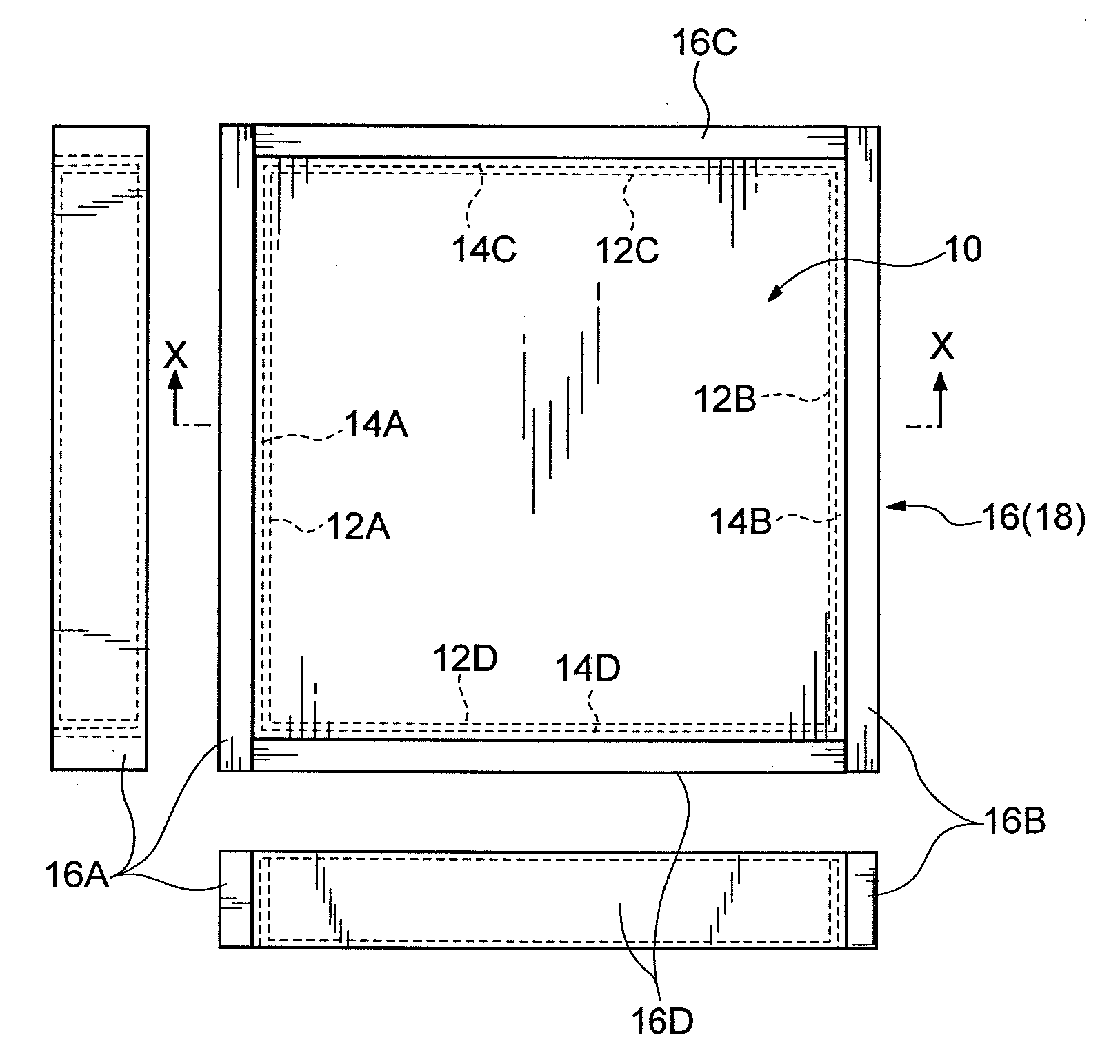
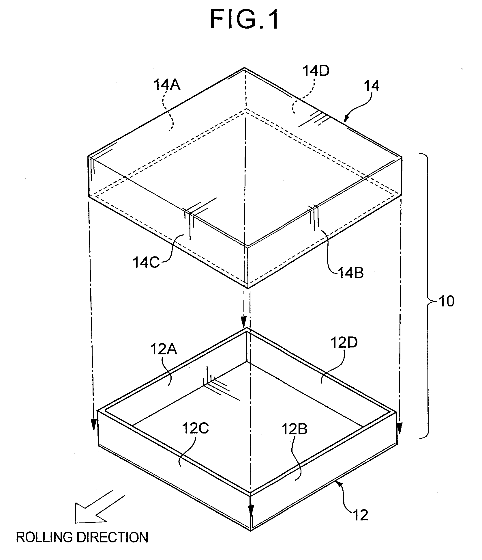
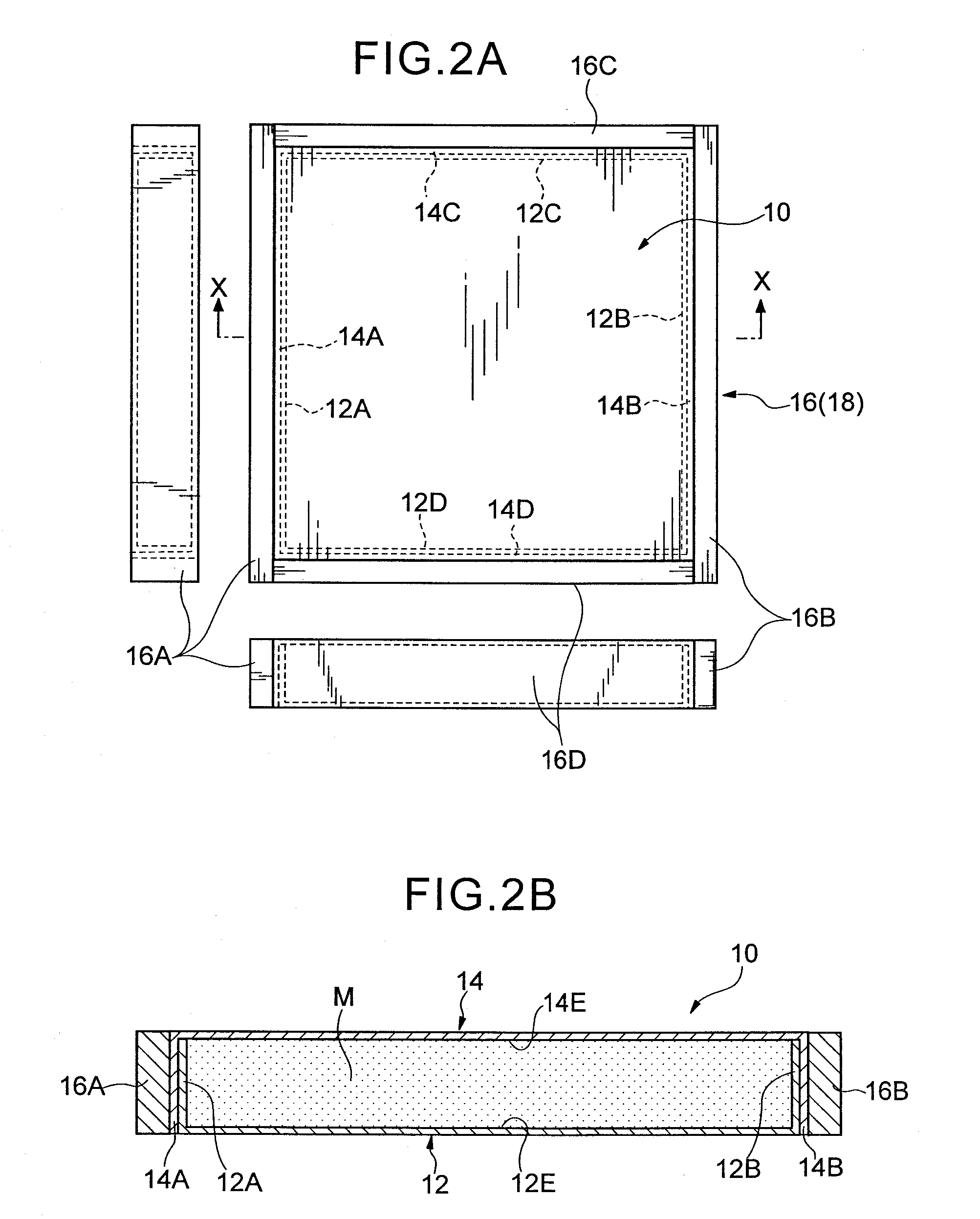
[0118]A B4C ceramic powder was uniformly mixed with an aluminum alloy powder having a composition as shown in Table 1, in an amount of 30 mass %, to prepare a powder mixture M. The aluminum alloy powder had an average particle size (D50) of 10 μm, and the B4C ceramic powder has an average particle size (D50) of 33 μm.

[0119]Then, a lower casing 12 made of an aluminum alloy (JIS A5052P) and formed in an approximately rectangular parallelepiped shape having outside dimensions of 367.7 mm on a side in square-shaped top and bottom surfaces, and 54.8 mm in height, and a wall thickness of 3.0 mm was prepared. Further, an upper casing 14 made of an aluminum alloy (JIS A5052P) and formed in an approximately rectangular parallelepiped shape having outside dimensions of 370.9 mm on a side in square-shaped top and bottom surfaces, and 57.8 mm in height, and a wall thickness of 3.0 mm was prepared. The aluminum alloy (JIS A5052P) had a tensile strength of 195 MPa. A composition of the aluminum a...


PUM

PropertyMeasurementUnit
particle sizeaaaaaaaaaa

Abstract

A metal matrix composite material comprising a pair of metal plates having a powder mixture disposed therebetween forming an intermediate layer is disclosed. Each of the metal plates having a main wall with opposed lateral walls on each end. The first of the metal plates having a main wall having a length greater than a length of the main wall of the second of the metal plates, so that the opposed lateral walls of the second metal plate are each disposed inside of a respective opposed lateral wall of the first metal plate. The powder mixture includes a metal powder and a ceramic powder. The ceramic powder has a neutron absorbing function, wherein the intermediate layer has a theoretical density ratio at least 98%, and a percentage of a total thickness of the metal plates to an overall thickness of the intermediate layer is in a range of 15 to 25%.

Description

CROSS-REFERENCE TO RELATED APPLICATIONS[0001]This application is a continuation-in-part application based on U.S. patent application Ser. Nos. 11 / 976,329; 11 / 976,330 and 11 / 976,331 all filed on Oct. 23, 2007. The subject matter of these applications is incorporated herein by reference.BACKGROUND OF THE INVENTION[0002]1. Field of the Invention[0003]The present invention generally relates to a metal matrix composite material having a neutron absorption capability, and more specifically, to a metal matrix composite material having excellent properties, such as plastic workability, thermal conductivity, room-temperature or high-temperature strength, high stiffness, wear resistance and low thermal expansibility.[0004]2. Description of the Related Art[0005]Heretofore, there has been known a method of producing a composite material having an aluminum matrix through a powder metallurgy process, comprising the steps of:[0006](1) mixing a powder of a ceramic material serving as a reinforcing ...

Claims


Application Information

Patent Timeline
Patent Type & Authority Applications(United States)
IPC IPC(8): B32B15/02B22F7/04
CPCB22F3/18B22F7/04B22F2003/185Y10T428/12083B32B15/016C22C21/06B32B15/013
Inventor ISHII, HIDEKINISHIYAMA, TOSHIMASASANADA, KAZUTOYAMAZAKI, TOSHIAKI
Owner NIPPON LIGHT METAL CO LTD
Why Eureka
Try Eureka