Clamping Part and Retention Device Having a Clamping Part of this Type

a technology of a retention or holder device and a clamping part, which is applied in the direction of threaded fasteners, screwing, machine supports, etc., can solve the problems of difficult to fix, difficult to fix, and difficult to change the retainer, etc., and achieve the effect of quick fixability

Inactive Publication Date: 2009-09-03
AIRBUS OPERATIONS GMBH
View PDF10 Cites 4 Cited by
  • Summary
  • Abstract
  • Description
  • Claims
  • Application Information

AI Technical Summary

Benefits of technology

[0005]An object of the present invention is to provide a clamping part and a holder device having a clamping part of this type, which is usable and rapidly attachable mutually on girders having different material thicknesses.
[0011]According to a refinement of the clamping part, the conical body has a gap in its side wall running in the longitudinal direction of the clamping par which connects the opening running through the center of the body to the environment of the clamping part. The clamping effect is thus improved further.
[0013]According to an exemplary embodiment, the holder device also contains a displacement lock, which is situated in the hollow base element to prevent the clamping part inserted into the hollow base element from falling out of the holder device.

Problems solved by technology

A disadvantage of the known retainers is that in the event of changes of the structural components, costly and time-consuming changes of the retainers are necessary.
The changes in injection molding molds are particularly complex and costly.

Method used


Image

  • Clamping Part and Retention Device Having a Clamping Part of this Type
  • Clamping Part and Retention Device Having a Clamping Part of this Type
  • Clamping Part and Retention Device Having a Clamping Part of this Type

Examples


Embodiment Construction

[0025]In the following, identical reference numerals are used for identical or corresponding parts in the different views in the figures.

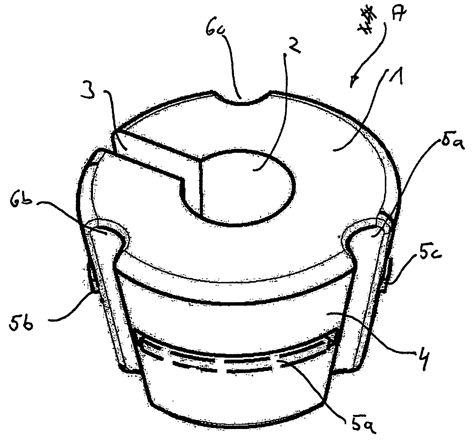
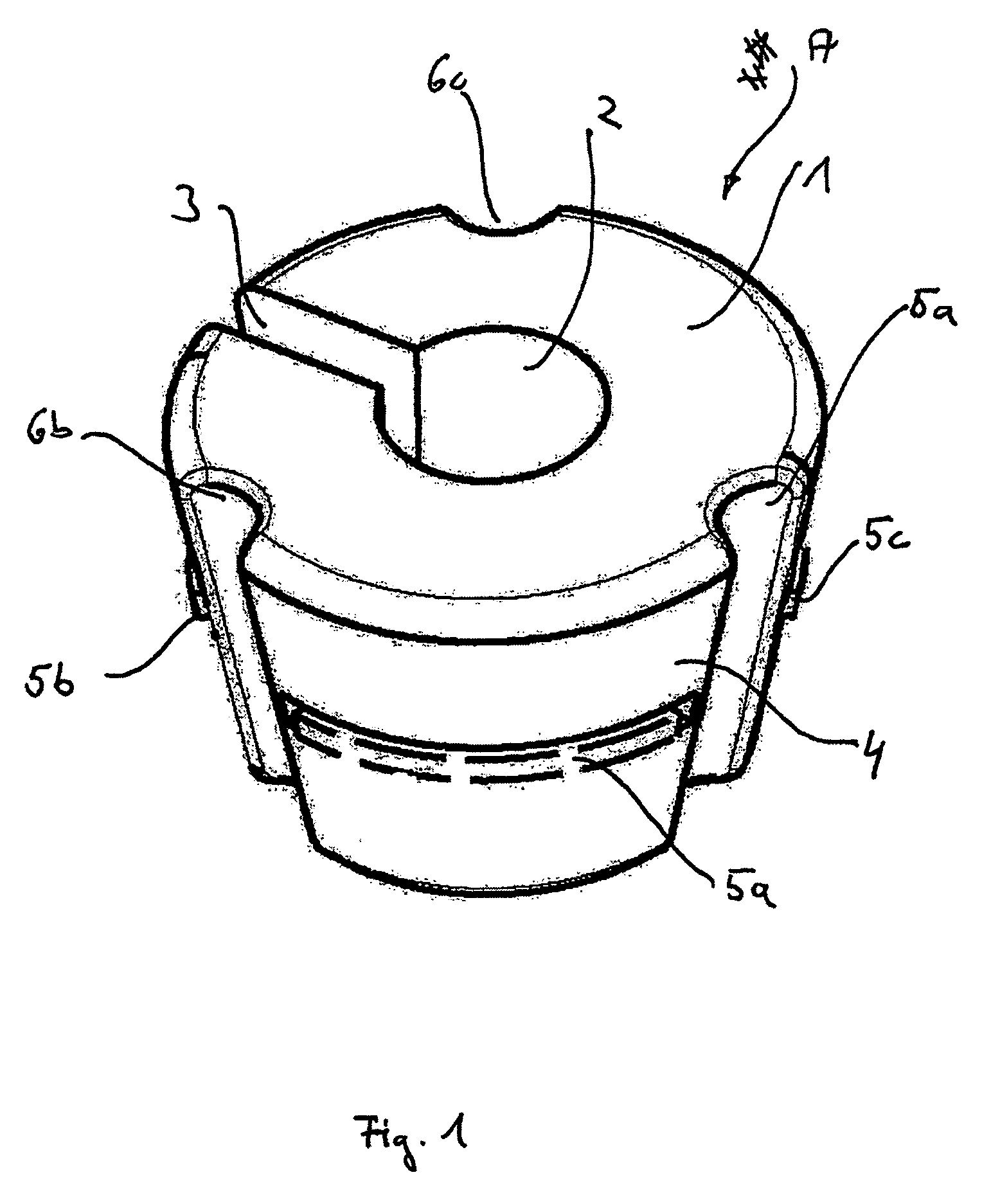
[0026]FIG. 1 shows a perspective view of a clamping part A according to an exemplary embodiment of the present invention.

[0027]As shown in FIG. 1, the clamping part A has a conical body 1, through whose center an opening 2 runs. As described later, the opening 2 is used for receiving a screw (not shown), to which a holder device which uses the clamping part A is attached, as described later with reference to FIG. 4.

[0028]The clamping part shown in FIG. 1 also has a gap 3, which connects the opening 2 to the external environment of the clamping part A. The gap 3 runs in the longitudinal direction of the clamping part A and is used for improving the clamping effect of the clamping part A. In the clamped state, the gap 3 is narrower than in the unclamped state.

[0029]Three separate slots 5a, 5b, and 5c are implemented in the side wall 4 of the clamping...


PUM


Abstract

A retaining device for attachment to a screw contains a hollow base element for receiving a clamping part. The hollow base element has a floor having a hole, and an inner surface of the base element on the floor area of the retaining device is implemented as conical to contact the outer surface of the conical body of the clamping part. The clamping part can be moved downward in the direction of the floor by rotating the retaining device around its own axis and biting into a screw which is inserted through the hole and runs through the opening of the clamping part.

Description

REFERENCE TO RELATED APPLICATIONS[0001]This application claims the benefit of the filing date of U.S. Provisional Patent Application No. 60 / 721 397 filed Sep. 28, 2005 and of German Patent Application No. 10 2005 046 362.2 filed Sep. 28, 2005, the disclosures of which are hereby incorporated herein by reference.FIELD OF THE INVENTION[0002]The present invention relates to a clamping part and a retention or holder device having a clamping part of this type, in particular a multipurpose holder for holding electrical wiring strands, pipes, etc. in aircraft.TECHNOLOGICAL BACKGROUND[0003]In aircraft, cable retainers are used for retaining and guiding electrical line routes, pipes, etc., in different areas. The retainers are preferably made of plastic because of its low intrinsic weight. The retainers are each tailored to the concrete connection conditions to the girders or frames, etc. For this purpose, a screw-nut connection is typically used.[0004]A disadvantage of the known retainers i...

Claims


Application Information

Patent Timeline
Patent Type & Authority Applications(United States)
IPC IPC(8): F16L3/08
CPCF16B2/14F16B3/06F16B9/026F16B37/0864F16B37/0828F16B37/0842F16B37/00F16B2200/406
Inventor KOSIANKOWSKI, LUEDERZEUNER, LUTZGUTHKE, HANS-PETER
Owner AIRBUS OPERATIONS GMBH
Why Eureka
Try Eureka