Quick attaching thermoelectric device

a thermoelectric device and quick technology, applied in the direction of thermoelectric device with peltier/seeback effect, thermoelectric device junction materials, electrical apparatus, etc., can solve the problems of limited useful life and not much success, and achieve the effect of quick attachment and improved thermal conductivity

Inactive Publication Date: 2006-11-30
HILLER NATHAN
View PDF4 Cites 17 Cited by
  • Summary
  • Abstract
  • Description
  • Claims
  • Application Information

AI Technical Summary

Benefits of technology

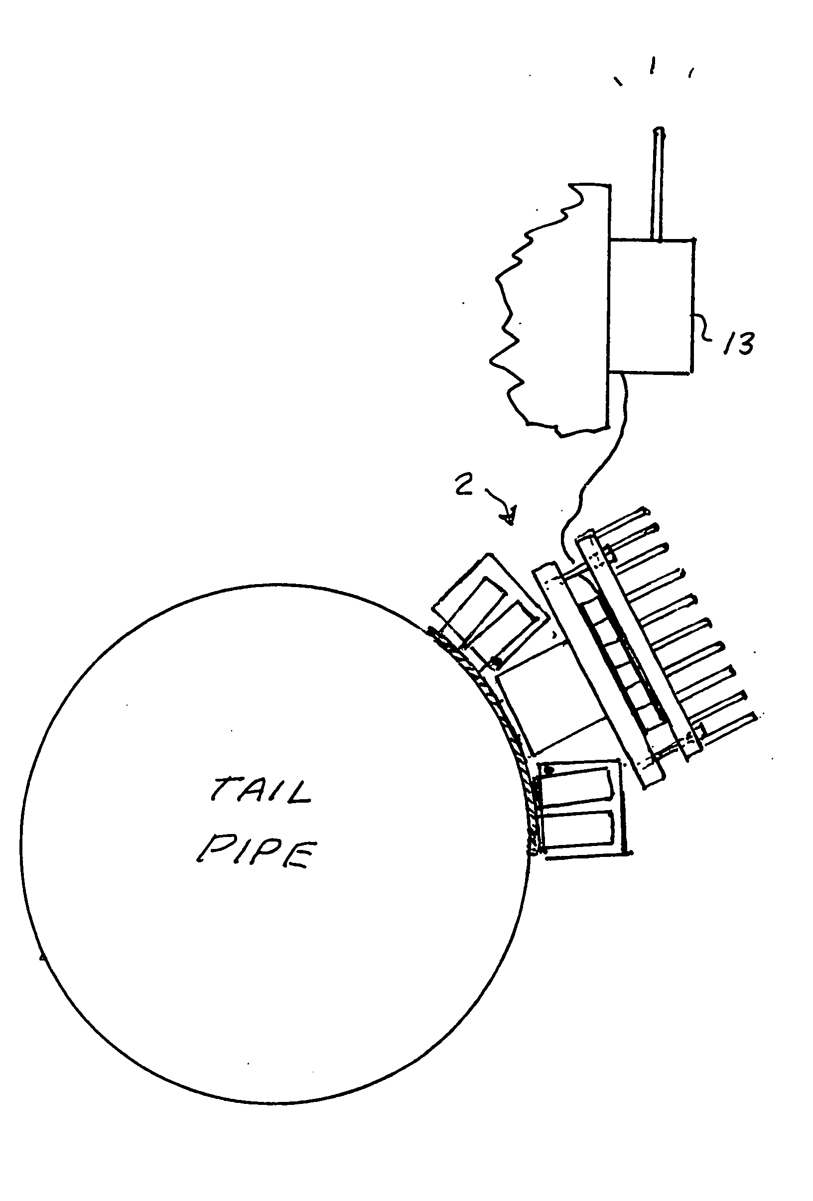
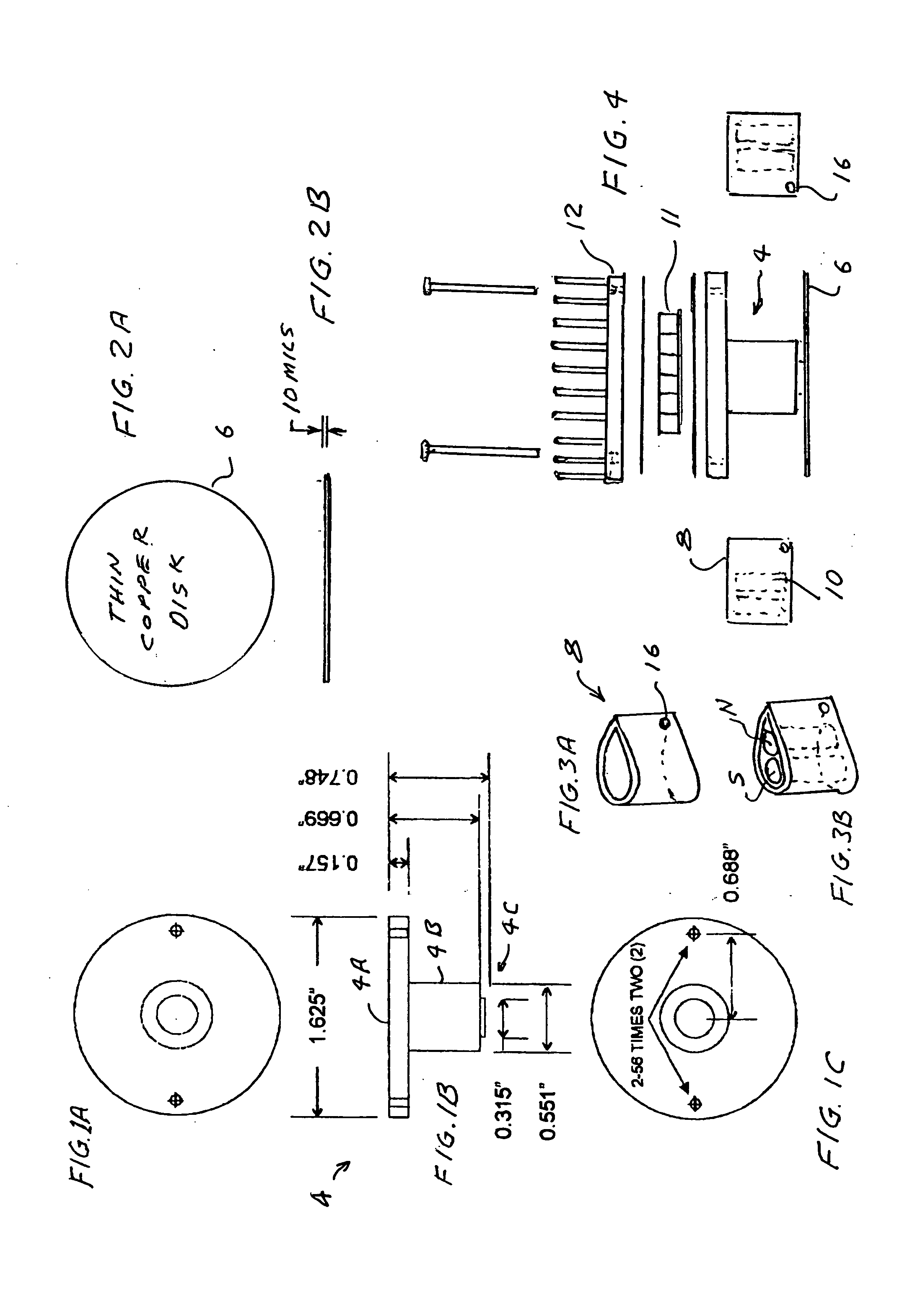
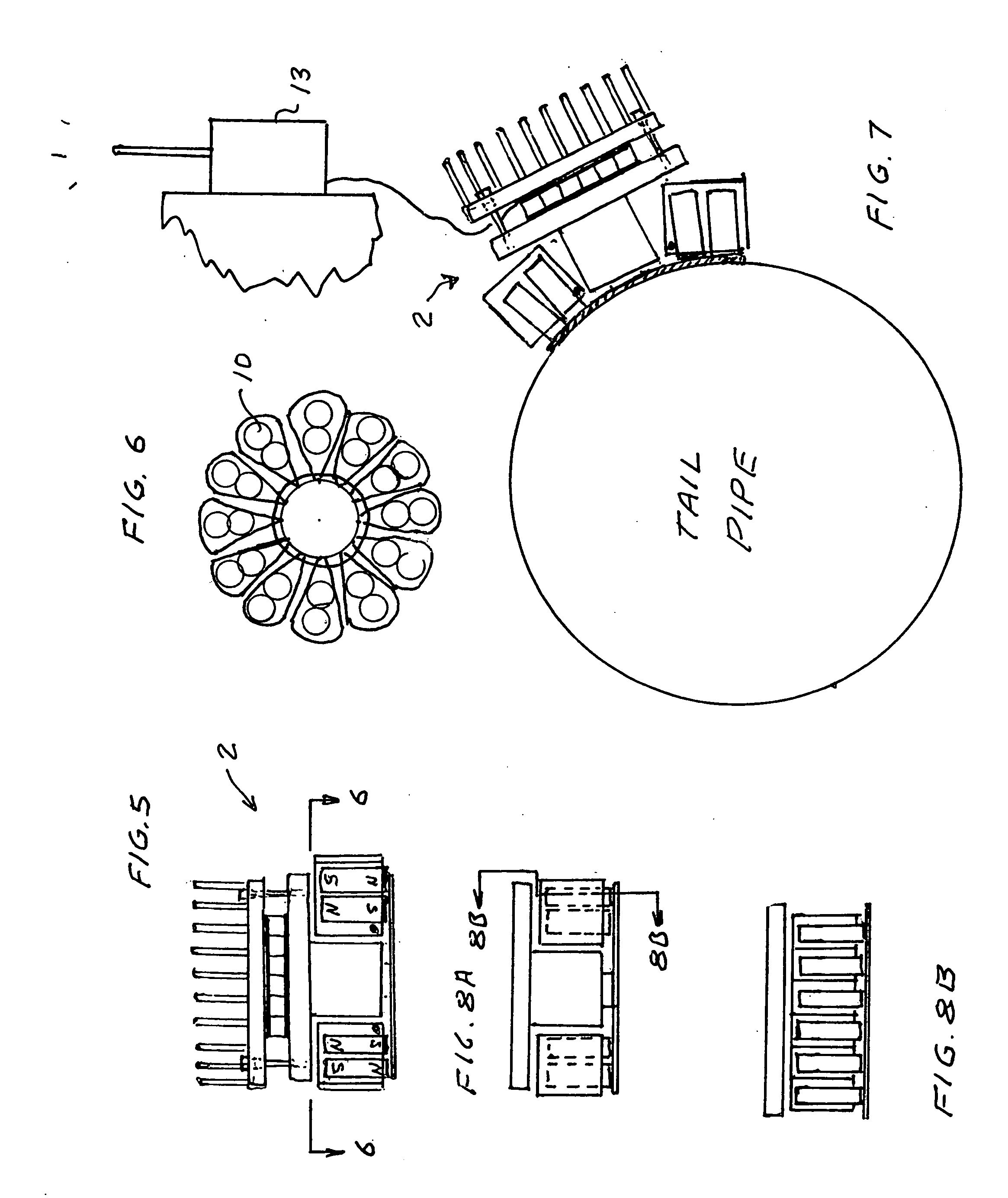
[0009] The present invention provides a quickly attachable electric generator system for producing electric power from hot or cold surfaces of magnetic materials. The system includes at least one permanent magnet for providing a magnetic attractive force to hold a surface of a thermoelectric module against the hot or cold surfaces. In a preferred embodiment, useful for attaching to the tail pipe or muffler of a motor vehicle, a thin flexible high heat conducting copper disk is braised to a thin bottom portion of a copper pedestal that has a wider flat upper portion. The wider flat upper portion is the heat source collector of a thermoelectric module that is compressed between it and an aluminum fin unit functioning as a heat sink. Insulating wafers on both the hot and cold sides to the thermoelectric module provide electrical insulation of the module from the copper pedestal and the finned heat sink. Heat conducting grease is used to improve thermal conductivity. In this preferred embodiment 24 small cylindrical magnets are positioned around a mid section of the pedestal in 12 aluminum bottomless cups positioned between the thin copper disk and the wide flat portion of the pedestal. When in use the thin flexible disk conforms to the surface shape of a steel (or other iron containing material) surface to which it is attached, and the disk along with the rest of the thermoelectric generator is held in place by the magnetic force of the 24 magnets. When attached to a tail pipe of a motor vehicle, heat flows from the hot surface of the tail pipe through the thin flexible copper disk, through the pedestal to provide a heat source at a temperature in the range of about 450 degrees F. for the thermoelectric module. The fin unit provides the heat sink transferring heat to the atmosphere to provide a “cold” surface at about 85 degrees for a temperature difference of about 365 degrees F. In this preferred embodiment the module is utilized to provide electric power to power a transmitter to transmit information regarding the location of the motor vehicle to which it is attached. Standard thermoelectric modules available on the market can be utilized.
[0010] For highest module efficiencies quantum well modules are preferred with p-legs and n-legs, each leg being comprised of a large number of at least two different very thin alternating layers of elements. For applications where the temperature range is relatively low, a preferred quantum well choice is n-doped Si / SiGe for the n-legs and p-doped Si / SiGe for the p-legs. At higher temperatures the preferred quantum well legs are alternating layers of silicon and silicon carbide for the n-legs and for the p-legs alternating layers of different stoichiometric forms of B-C.

Problems solved by technology

Workers in the thermoelectric industry have been attempting too improve performance of thermoelectric devices for the past 20-30 years with not much success.
These devices are typically powered by batteries so that their useful life is limited.

Method used


Image

  • Quick attaching thermoelectric device
  • Quick attaching thermoelectric device
  • Quick attaching thermoelectric device

Examples


first preferred embodiment

[0014]FIGS. 1A through 7 show the basic features of a first preferred embodiments of the present invention. In this embodiment a thermoelectric generator is attached to a cylindrical steel tail pipe of a motor vehicle with the magnetic force of a plurality of magnets that compresses a thin flexible high heat conducting element against the tail pipe. Preferably, the thin flexible high heat conducting element is a thin copper disk and it is braised to a thin bottom portion of a copper pedestal that has a wider flat upper portion. The wider flat upper portion is the heat source of a thermoelectric module that is compressed between an aluminum fin unit functioning as a heat sink and the flat upper portion of the pedestal. Insulating wafers on both the hot and cold sides to the thermoelectric module provide electrical insulation of the module from the copper pedestal and the finned heat sink. Heat conducting grease is used to improve thermal conductivity. In this preferred embodiment 24 ...

second preferred embodiment

[0016] A second preferred embodiment of the present invention is shown in FIGS. 8A and 8B. This unit is exactly the same as the generator of the first preferred embodiment except the thin bottom part of pedestal 4 is rectangular rather than circular. This second preferred embodiment is useful for attachment to flat and cylindrical surfaces but would not attach very well to spherical surfaces. Also, when attaching it to cylindrical surfaces care must be taken to line it up with the axis of the cylindrical surface. It should attach very well however to tail pipes and mufflers of motor vehicles.

[0017] While the above description contains many specificities, the reader should not construe these as limitations on the scope of the invention, but merely as exemplifications of preferred embodiments thereof. Those skilled in the art will envision many other possible variations within its scope. For example: [0018] The bismuth telluride N and P legs used in the thermoelectric module can be r...


PUM


Abstract

A quickly attachable electric generator system for producing electric power from hot or cold surfaces of magnetic materials. The system includes at least one permanent magnet for providing a magnetic attractive force to hold a surface of a thermoelectric module against the hot or cold surfaces. In a preferred embodiment, useful for attaching to the tail pipe or muffler of a motor vehicle, a thin flexible high heat conducting copper disk is braised to a thin bottom portion of a copper pedestal that has a wider flat upper portion. The wider flat upper portion is the heat source of a thermoelectric module that is compressed between it and an aluminum fin unit functioning as a heat sink. Insulating wafers on both the hot and cold sides to the thermoelectric module provide electrical insulation of the module from the copper pedestal and the finned heat sink. Heat conducting grease is used to improve thermal conductivity. In this preferred embodiment 24 small cylindrical magnets are positioned around a mid section of the pedestal in 12 aluminum bottomless cups positioned between the thin copper disk and the wide flat portion of the pedestal. When in use the thin flexible disk conforms to the surface shape of the steel (or other iron containing material) to which it is attached, and the disk along with the rest of the thermoelectric generator is held in place by the magnetic force of the 24 magnets. When attached to a tail pipe heat flows from the hot surface of the tail pipe through the thin flexible copper disk, through the pedestal to provide a heat source at a temperature in the range of about 450 degrees F. for the thermoelectric module. The fin unit provides the heat sink transferring heat to the atmosphere to provide a cold surface at about 85 degrees for a temperature difference of about 365 degrees F. In this preferred embodiment the module is utilized to provide electric power to power a transmitter to transmit information regarding the location of the motor vehicle to which it is attached. Standard thermoelectric modules available on the market can be utilized.

Description

[0001] The present invention relates to thermoelectric devices and in particular techniques for producing electric power from existing heat sources. BACKGROUND OF THE INVENTION [0002] A well-known use for thermoelectric devices is for the extraction of electric power from waste heat. For example, U.S. Pat. No. 6,527,548 discloses a self powered space heater for a truck in which heat energy for the heater is used to power electric components of the heater plus charge a battery. In U.S. Pat. No. 6,053,163 heat from a stovepipe is used to generate electricity. U.S. Pat. No. 6,019,098 discloses a self-powered furnace. Various types of thermoelectric modules are available. A very reliable thermoelectric module with a gap-less egg-crate design is described in U.S. Pat. Nos. 5,875,098 and 5,856,210. U.S. Pat. No. 6,207,887 discloses a miniature milli-watt thermoelectric module useful in space applications (and special applications on earth) in combination with radioactive heat source. [000...

Claims


Application Information

Patent Timeline
Patent Type & Authority Applications(United States)
IPC IPC(8): H01L35/30
CPCH01L35/00H01L35/30H01L35/22H10N10/00H10N10/855H10N10/13
Inventor HILLER, NATHAN
Owner HILLER NATHAN
Why Eureka
Try Eureka