Locomotive hand brake tools

a technology of hand brakes and hand brakes, which is applied in the direction of mechanical control devices, instruments, process and machine control, etc., can solve the problems of railroad workers' fingers being seriously injured, unsafe conditions created, and too much force to utilize this method

Active Publication Date: 2013-09-12
MONROE THOMAS P
View PDF16 Cites 4 Cited by
  • Summary
  • Abstract
  • Description
  • Claims
  • Application Information

AI Technical Summary

Benefits of technology

[0017]On preferred versions of the invention having three jaws, the jaws bear against the inner surface of the junction of the outer handwheel rim and one of the handwheel spokes. The jaws transmit multidirectional force to the handwheel rim. This is possible because, as the drawbar is tightened, each of t...

Problems solved by technology

By trying to spin the handwheel with two or three fingers, an unsafe condition is created if the handwheel should suddenly stop and lock up.
Some wheels offer continuous resistance to free spinning, and require too much force to utilize this method.
This situation could also result in serious injury to the railroad worker's fingers.
Should the locomotive handbrake handwheels have a permanently mounted handgrip on the handwheel, the handgrip would create a tripping or im...

Method used


Image

  • Locomotive hand brake tools
  • Locomotive hand brake tools
  • Locomotive hand brake tools

Examples


Embodiment Construction

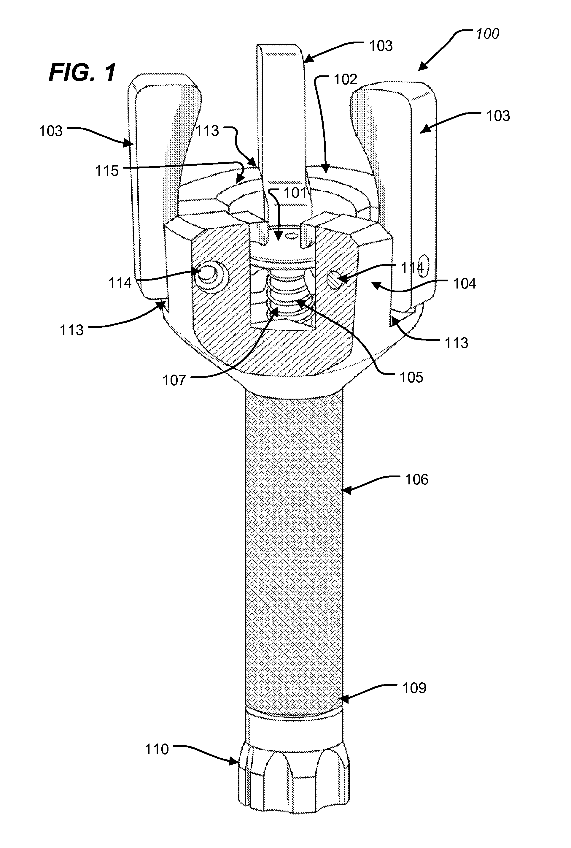
[0029]FIG. 1 is a top perspective view of a tool according to one embodiment. The depicted tool 100 includes a handle 106 attached to a tool body, the main part of the tool body being the tool body structure 104. A cutout area is shown in tool body structure 104 in order to depict the inner parts of the tool head, but this is only for illustrative purposes and the preferred embodiment has a solid circular shape with the cutout area filled in.

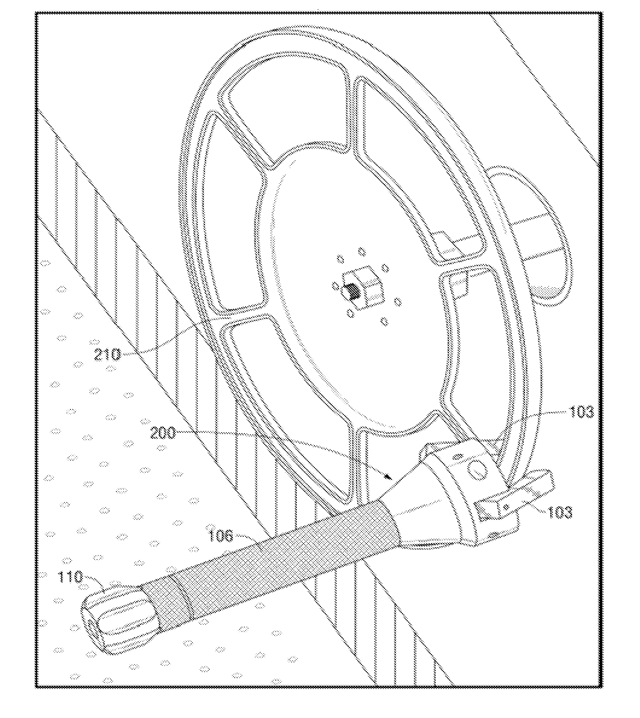
[0030]This tool 100 is employed to provide a handle extension to the existing locomotive handbrake wheel. It serves as a useful tool to help remove the extreme amount of slack in handbrake chain. However, this tool is not a leverage increasing device, as one of the inventor's prior applications is directed to. The tool also provides improved safety by allowing a safe and secure hand placement option that will prevent injuries to employees' fingers while rotating the handbrake wheel. When the tool is attached to a handbrake handwheel (as shown in...


PUM


Abstract

An extension tool is provided for operating handwheels, such as those found on locomotive handbrakes. The tool includes a spinning handle and a tool body. The handle freely rotates about a longitudinal axis and provides a user with a spinning grip, allowing him or her to quickly and easily turn a handwheel. The tool body includes two or more jaws that clamp to the handwheel. The tool body additionally includes a screw mechanism for selectively tightening or releasing the jaws, in order to respectively attach or detach the tool from the handwheel as desired. Preferably, the screw mechanism further includes a drawbar that extends through an interior of the handle, and is adapted to move longitudinally to rotate the jaws. The drawbar is moved by rotating a threaded drawbar nut at an end of the tool.

Description

TECHNICAL FIELD OF THE INVENTION[0001]The present invention relates to handheld extension tools, and more particularly to extension tools for operating a hand wheel associated with a handbrake used on a railroad locomotive.BACKGROUND OF THE INVENTION[0002]This invention relates to the field of tools used in the railroad industry by locomotive engineers to aid in the application release of locomotive engine vertical handwheel handbrakes. The operation of locomotive handbrakes is, in principle, the same as the handbrakes used on railroad cars. Application of the brakes means to set the handbrake to a “stop” position in which the locomotive will not move accidentally. Release of the brake means to set the handbrake to an “off” position in which the locomotive can be safely moved.[0003]Locomotive handbrakes are placed on locomotives to be used in addition to the locomotive air brakes to keep the locomotives from moving while not in use, should the locomotive air brakes fail or be accide...

Claims


Application Information

Patent Timeline
IPC IPC(8): G05G1/10
CPCY10T74/20864G05G1/04B25B13/28B25B13/44
Inventor MONROE, THOMAS P.
Owner MONROE THOMAS P
Why Eureka
Try Eureka