Rotating vehicle seat

Inactive Publication Date: 2009-09-03
AUTECH JAPAN INC
View PDF6 Cites 3 Cited by
  • Summary
  • Abstract
  • Description
  • Claims
  • Application Information

AI Technical Summary

Benefits of technology

[0008]The present invention was conceived in view of these problems and its object is to provide a rotating vehicle seat that can achieve a greater degree of simplification.
[0023]More specifically, when the seat body is in a state of having been returned to a pre-rotation position, looseness of the seat body is prevented by a looseness preventing structure configured to prevent looseness of the seat body by means of a fitting together of the first and second members.

Problems solved by technology

Consequently, the proposed rotating vehicle seat takes up layout space and the wiring arrangement and control thereof is complex.

Method used


Image

  • Rotating vehicle seat
  • Rotating vehicle seat
  • Rotating vehicle seat

Examples


Embodiment Construction

[0037]A selected embodiment of the present invention will now be explained with reference to the drawings. It will be apparent to those skilled in the art from this disclosure that the following description of the embodiment of the present invention is provided for illustration only and not for the purpose of limiting the invention as defined by the appended claims and their equivalents.

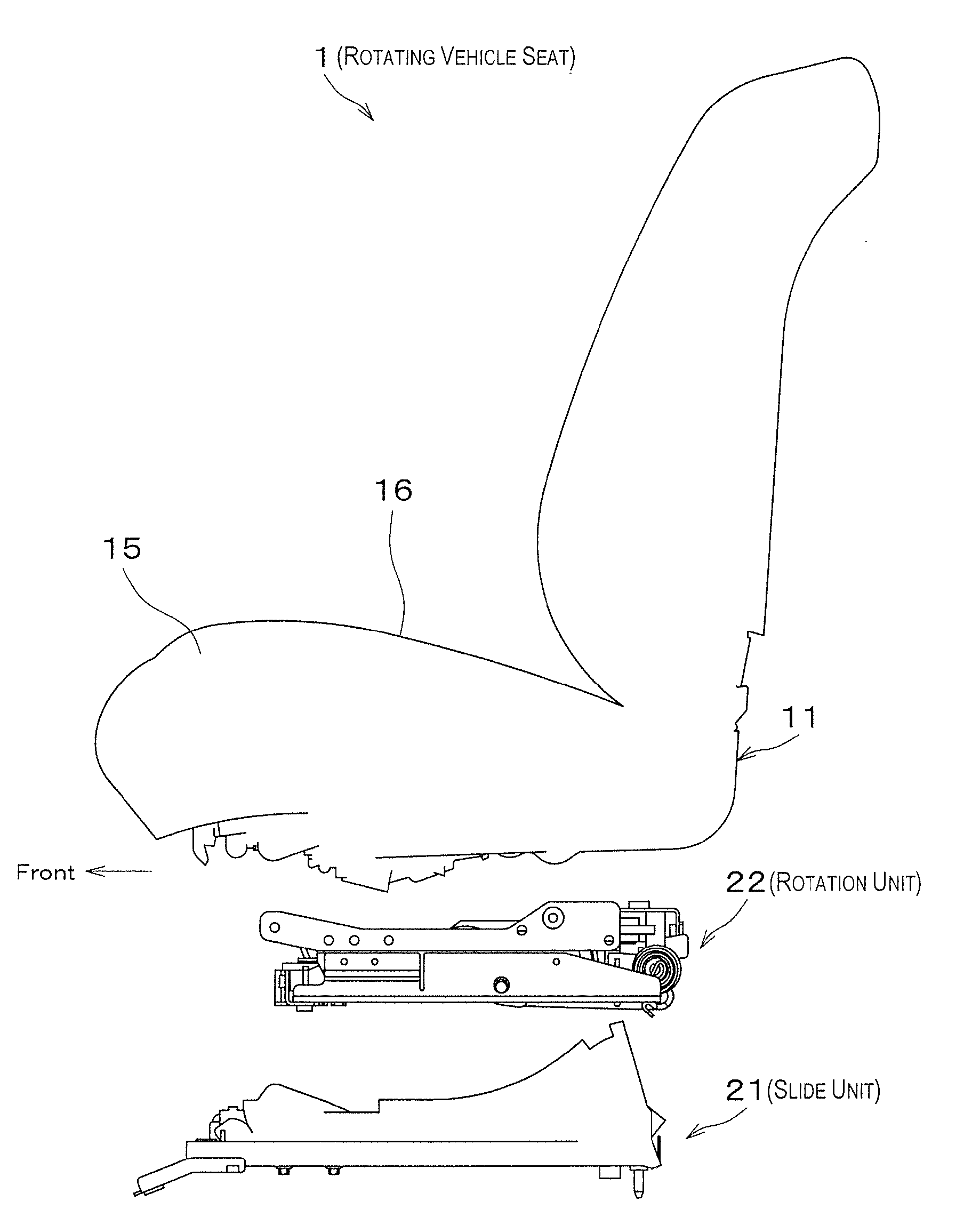
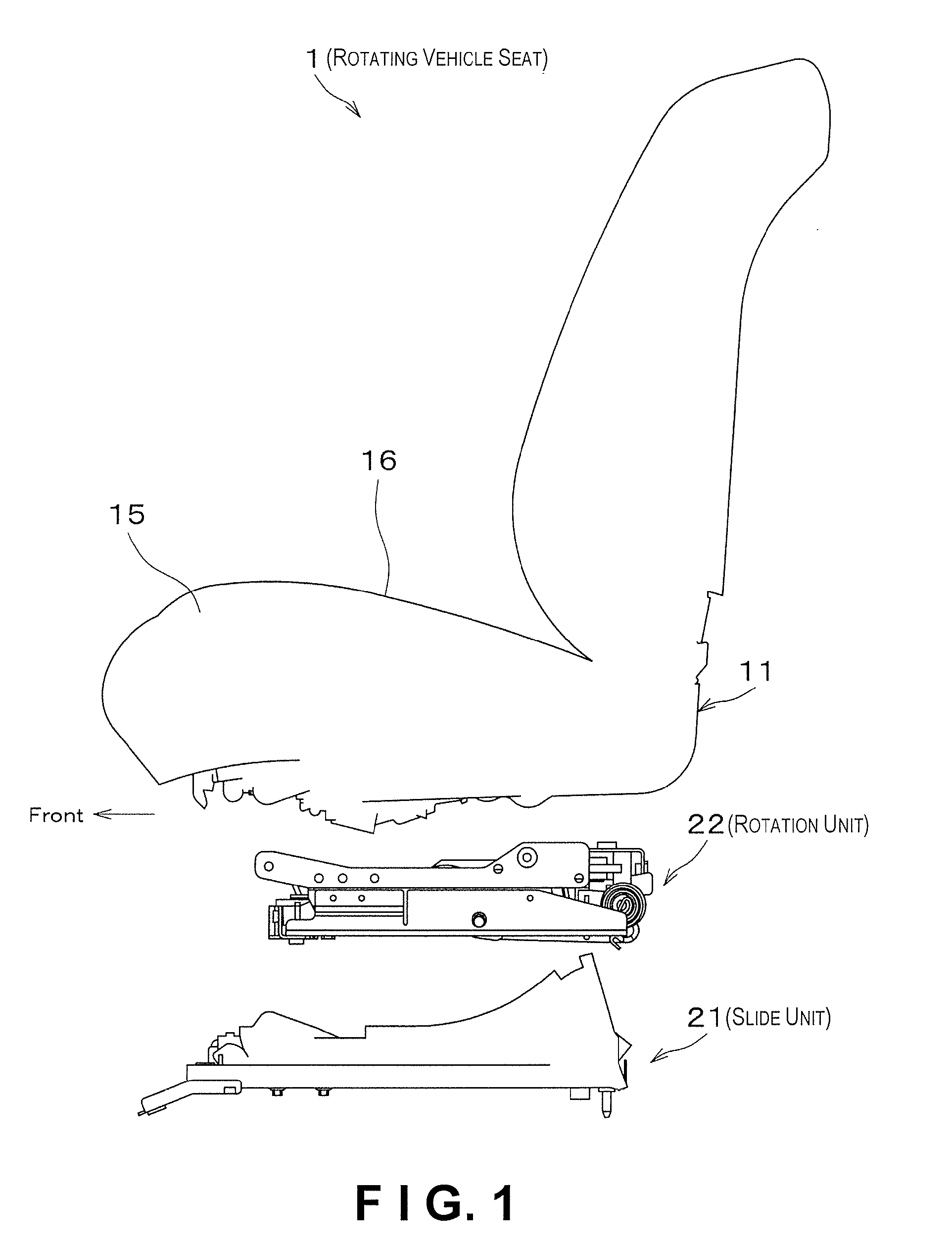
[0038]FIG. 1 is shows a rotating vehicle seat 1 in accordance with the embodiment.

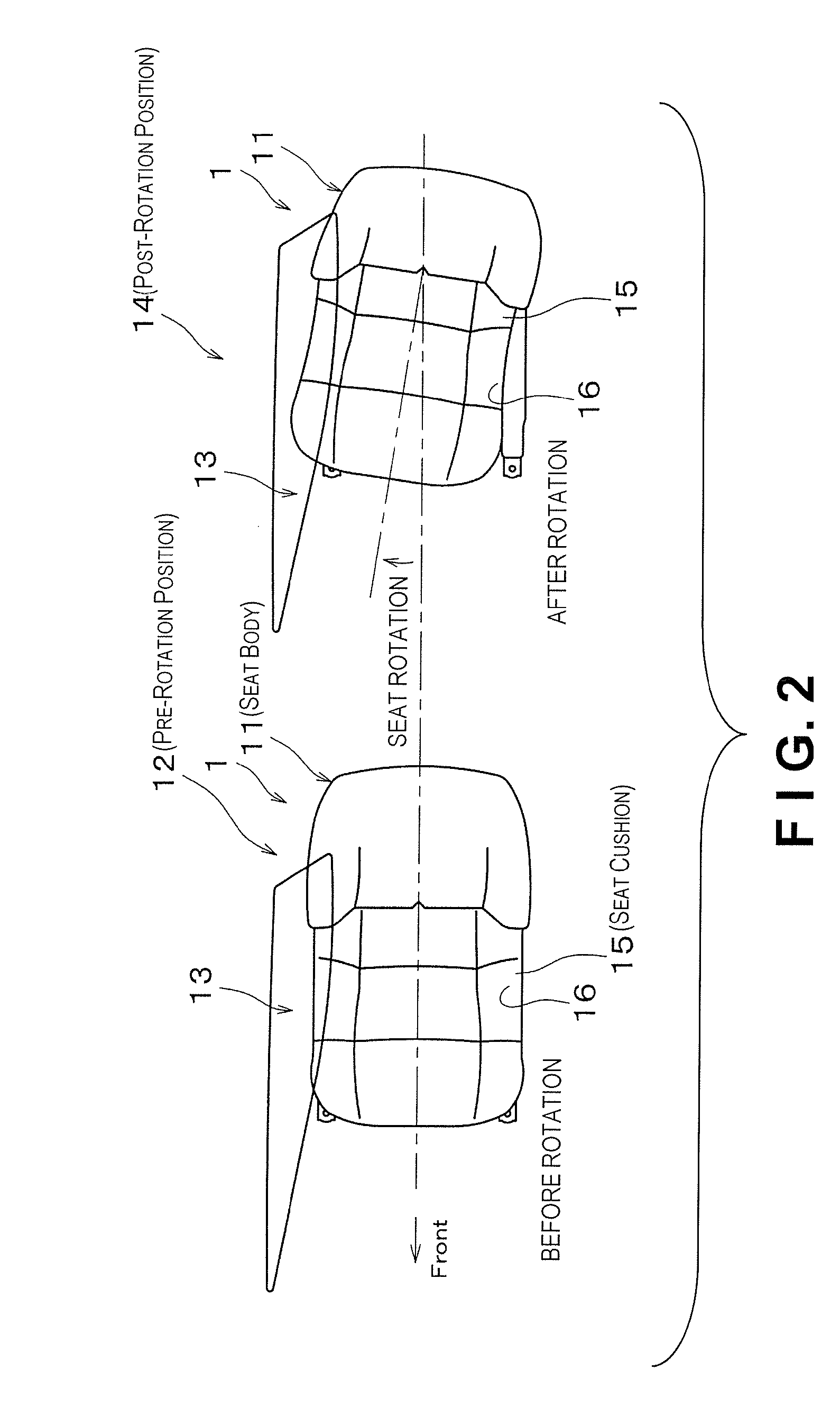
[0039]As shown in FIG. 2, the rotating vehicle seat 1 is installed as a driver's seat of a vehicle and includes a seat body 11 serving as a seat portion on which a driver sits. The rotating vehicle seat 1 is contrived such that the seat body 11 can be rotated between a pre-rotation position 12 in which the seat body 11 faces toward a front F of the vehicle and a post-rotation position 14 in which the seat body 11 faces toward an embarkation opening 13 provided in a right side portion of the vehicle. Additionally, as sho...


PUM


Abstract

A rotating seat for a vehicle includes a seat surface tilt angle varying mechanism, a seat surface rotating mechanism and a single drive source. The seat surface tilt angle varying mechanism is configured and arranged to vary a tilt angle of a seat surface of a seat body. The seat surface rotating mechanism is configured and arranged to rotate the seat surface. The drive source is configured and arranged to drive the seat surface tilt angle varying mechanism and the seat surface rotating mechanism.

Description

CROSS-REFERENCE TO RELATED APPLICATIONS[0001]This application claims priority to Japanese Patent Application No. 2008-048988, filed on Feb. 29, 2008. The entire disclosure of Japanese Patent Application No. 2008-048988 is hereby incorporated herein by reference.BACKGROUND OF THE INVENTION[0002]1. Field of the Invention[0003]The present invention relates to a rotating vehicle seat provided in a vehicle.[0004]2. Background Information[0005]Japanese Laid-Open Patent Application Publication No. 2004-34908 discloses a conventional rotating vehicle seat configured such that a seat main body can be rotated relative to a vehicle. This conventional rotating vehicle seat has a rotating mechanism configured to rotate a seat surface of the vehicle seat between a normal position in which the seat faces toward a front of the vehicle and an embarkation position in which the seat faces toward an embarkation opening. By rotating to the embarkation position, the rotating vehicle seat enables a passen...

Claims


Application Information

Patent Timeline
IPC IPC(8): B60N2/02
CPCB60N2002/0256B60N2/14B60N2/0256
Inventor FUKUIIGAKURA, TETSUYANAGAO, YUASAI, HIDEYUKI
Owner AUTECH JAPAN INC
Why Eureka
Try Eureka