
Telescopic rod for handling a tool

a technology of telescopic rods and tools, which is applied in the field of telescopic rods for handling tools, can solve the problems of frequent maintenance, heavy weight, and bulky hydraulic or pneumatic cylinders that cannot power telescopic rods for the above applications, and achieves the effects of low wear, low vibration, and high reliability

Active Publication Date: 2016-10-25
GB PROGETTI SRL
View PDF21 Cites 7 Cited by
  • Summary
  • Abstract
  • Description
  • Claims
  • Application Information

AI Technical Summary

Benefits of technology

The present invention provides a telescopic rod for raising small objects that has limited vibrations, high reliability, and can be raised and lowered quickly without damaging parts. It is also easy and light to use.

Problems solved by technology

However, hydraulic or pneumatic cylinders would be too bulky and heavy to power telescopic rods for the above applications.
The presence of racks and gears determines risk of jamming and blocking the relative movement, and therefore frequent maintenance.
A disadvantage of the pruner disclosed in U.S. Pat. No. 4,924,573 is that, in order to increase the length of the rod extension, also the worm drive has to be correspondingly long.
However, a long worm drive would vibrate transversally very intensely and would hit against the housing within the hollow base and also with the rod extension, disengaging from the rack.
This would cause rapid wear and break of the worm drive.
Another limit is that the worm drive rotation has to be significantly limited, to avoid the transversal vibration.
However, this causes the extension / withdrawal speed to be very low, with a loss of most of the advantages of having a motorised telescopic rod.

Method used


Image

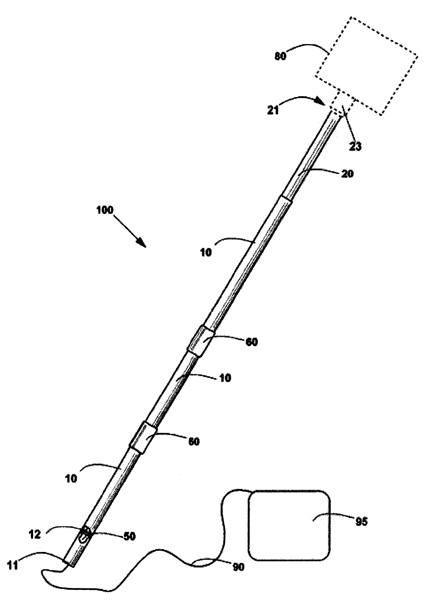
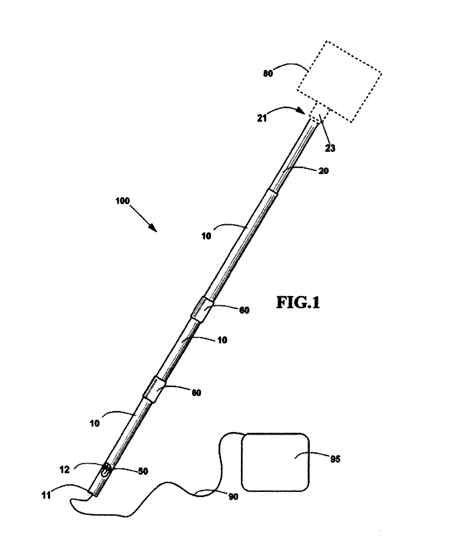
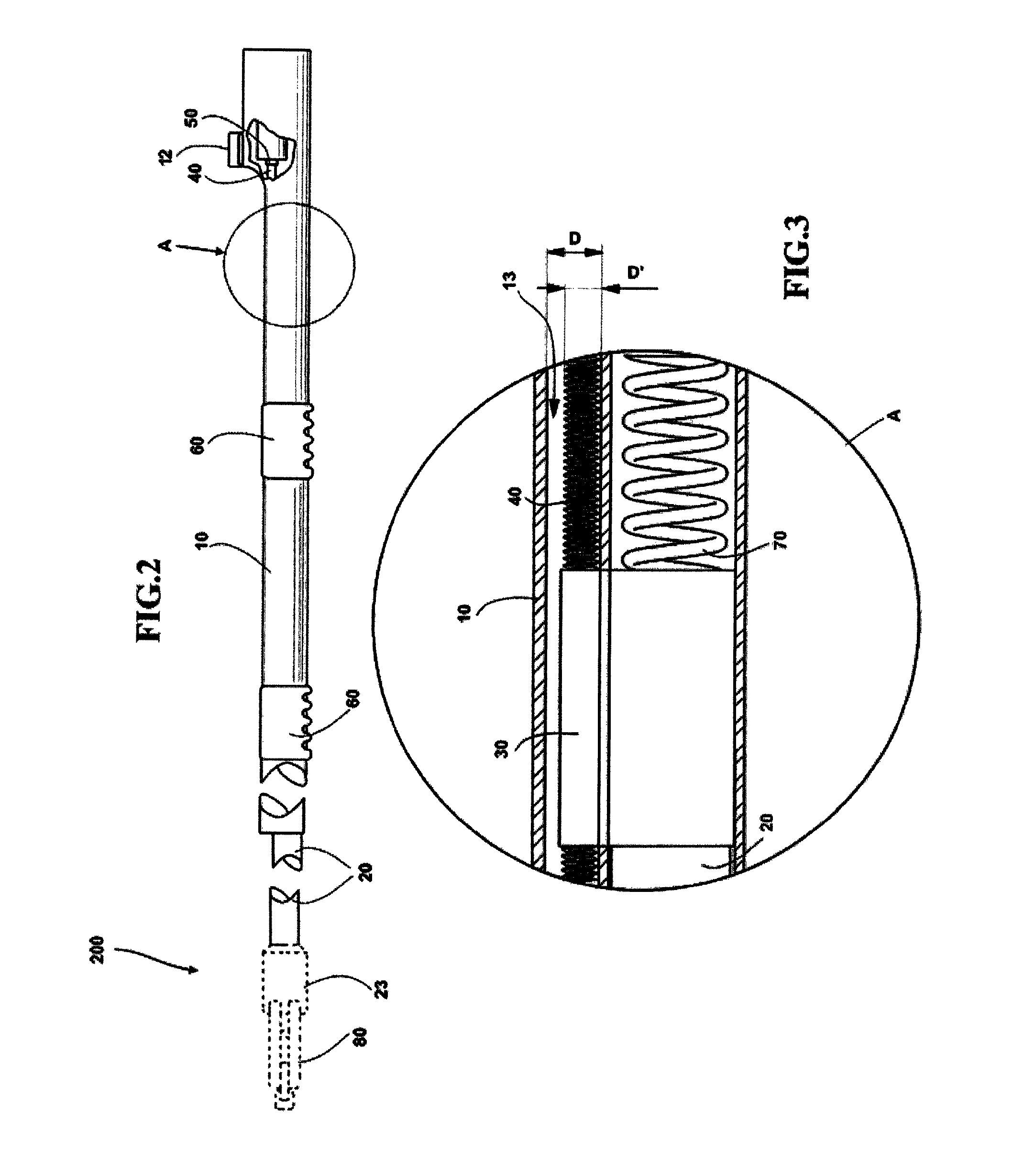
  • Telescopic rod for handling a tool
  • Telescopic rod for handling a tool
  • Telescopic rod for handling a tool

Examples


first embodiment

[0098]In a first embodiment, not shown, the anti-rotation means comprises a protrusion or a recess made along rod extension, and a recess or a protrusion, respectively, made along rod base, that engage with each other avoiding a relative rotation of the rod extension with respect to the rod base.

second embodiment

[0099]In a second embodiment, with reference to FIGS. 18 to 19, the anti-rotation means comprises a telescopic rod 500 still equipped with a pneumatic or hydraulic actuation means of the type described with reference to telescopic rod 400 of FIG. 17. Telescopic rod 500 comprises a base casing 540 and an extension casing 541, integral to rod base 10 and, respectively, to rod extension 20. More in detail, base casing 540 and extension casing 541 are arranged in such a way to engage telescopically one with each other, in order to guide the rod extension and the rod base and to avoid any rotation of the rod extension with respect to the rod base. In particular, the base casing and the extension casing can have a longitudinal protrusion / recess engaging one with each other, or have, preferably, a shaped cross-section, for example hexagonal, by which reciprocal rotation is impeded.

[0100]To connect the supported tool to a power source, an electric or pneumatic or hydraulic connection is als...


PUM


Abstract

A telescopic rod in order to use objects or tools at a desired height above the head of a user, in particular for harvesting fruit from trees or for pruning tree branches or painting high walls or ceilings, comprises a rod base with a base end, a rod extension slidingly engaging with the rod base, a support member configured to support a tool, arranged at a support end of the rod extension opposite to the rod base, an actuation means to automatically push / pull the rod extension with respect to the rod base, a rod actuation command at said base end to operate the actuation means between a push position, in which the actuation means pushes said rod extension to elongate said rod, a pull position, in which the actuation means pulls the rod extension to shorten the rod, a standby position in which the actuation means is inoperative and the rod can be used at a desired rod length to maneuver the tool at a desired height.

Description

FIELD OF THE INVENTION[0001]The present invention relates to a telescopic rod for handling a tool, for example for household or industrial use, or for agricultural use, for example an elongated handle, in particular to operate an harvesting or a cutting tool at a desired height above the head of a user.[0002]The rods of this type have a gripping end which can be gripped by a user, and a holding end, where the tool can be supported, in such a way that the user can bring the tool to a desired location above the head of a user by the rod. The rod has a gripping rod member and a holding rod member, which are engaged in a telescopic way with each other.BACKGROUND OF THE INVENTION[0003]Telescopic rods of the above mentioned type are known of many kinds. They differ from each other in the way for which they are arranged to increase or reduce their length and in the way for which they are locked / released at a desired length.[0004]They can be used for handling a tool at a desired height abov...

Claims


Application Information

Patent Timeline
Patent Type & Authority Patents(United States)
IPC IPC(8): B25G1/04
CPCB25G1/04Y10T16/473
Inventor BALESTRIERI, RITA
Owner GB PROGETTI SRL
Learn More