Burner for a heater with improved fuel supply, improved heat shield and improved baffle plate

Inactive Publication Date: 2009-09-03
WEBASTO AG
View PDF6 Cites 3 Cited by
  • Summary
  • Abstract
  • Description
  • Claims
  • Application Information

AI Technical Summary

Benefits of technology

[0010]The object of the invention is to overcome the described problems of the prior art at least in part and especially to enable reliable and low-emission starting behavior with little dense smoke in different installation positions.
[0016]It is useful for the air guide elements to be formed by tabs which are made integrally with the heat shield and which project in the direction of the combustion chamber. This heat shield can be easily produced, for example, by the tabs being formed with a V-shaped punching tool and being bent out of the plane of the heat shield after or with the punching process.
[0017]The invention is also usefully developed in that the tabs are made at different angles relative to the surface of the heat shield and / or to the radius of the heat shield. If the tabs extend almost perpendicularly to the radius of the heat shield, this delivers strong angular momentum, while tabs with a smaller angle to the radius deliver smaller angular momentum. Tabs which assume a small angle to the surface of the heat shield produce air flows which have a large radial component and a small axial component, while for tabs with large angles to the surface of the heat shield the axial component dominates. In this way, it is possible to route secondary air with low angular momentum into the core region of flame formation. Thus, the air required for combustion is supplied; but there is no excess angular momentum which would adversely affect stabilization of the flame. In particular, the secondary air can be divided depending on the alignment of the individual air guide elements.
[0019]The invention is also usefully executed such that the burner has a burnout zone and that the secondary air which is supplied to the burnout zone has higher angular momentum than the secondary air which is supplied to the starting zone. High angular momentum is desired in the burnout zone. In particular a radially inside swirled backflow region improves the burnout and provides for the combustion chamber volume being effectively used.
[0020]It is preferred that there is a curvature in the direction of the burnout zone. In this way, a sufficient space in the region of the starting chamber is made available. Furthermore, it has been found that the curvature in the direction of the burnout zone does not have an adverse effect on the flow behavior in this zone. In particular, the pronounced swirled backflow region is maintained in the radially inside region of the burnout zone.
[0023]The invention is based on the finding that the novel fuel supply with a fuel needle with a reduced exit cross section, the novel heat shield with air guide elements and the novel, curved baffle plate can greatly improve the operating behavior of a burner. This relates especially to the starting behavior, the stability of burner operation and possibilities with respect to the installation position of the burner in the motor vehicle.

Problems solved by technology

In particular, for a small primary air amount, for which the supplied primary air should have only little angular momentum, an essentially unatomized fuel jet can reach the starting zone.
For the baffle plates of the prior art which are made flat, this is among others not the case since depending on the temperature spontaneous changes of shape can occur which can adversely affect the combustion behavior of the burner.

Method used


Image

  • Burner for a heater  with improved fuel supply, improved heat shield and improved baffle plate
  • Burner for a heater  with improved fuel supply, improved heat shield and improved baffle plate
  • Burner for a heater  with improved fuel supply, improved heat shield and improved baffle plate

Examples


Embodiment Construction

[0028]In the following description of preferred embodiments of the invention, the same reference numbers label the same or comparable components.

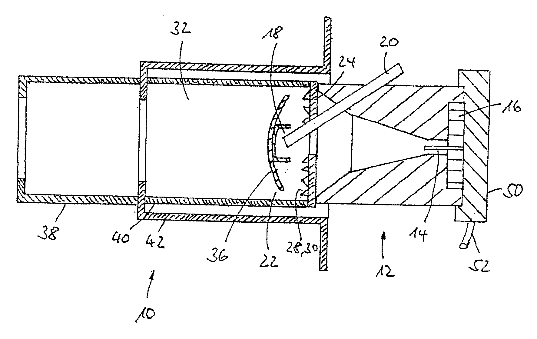
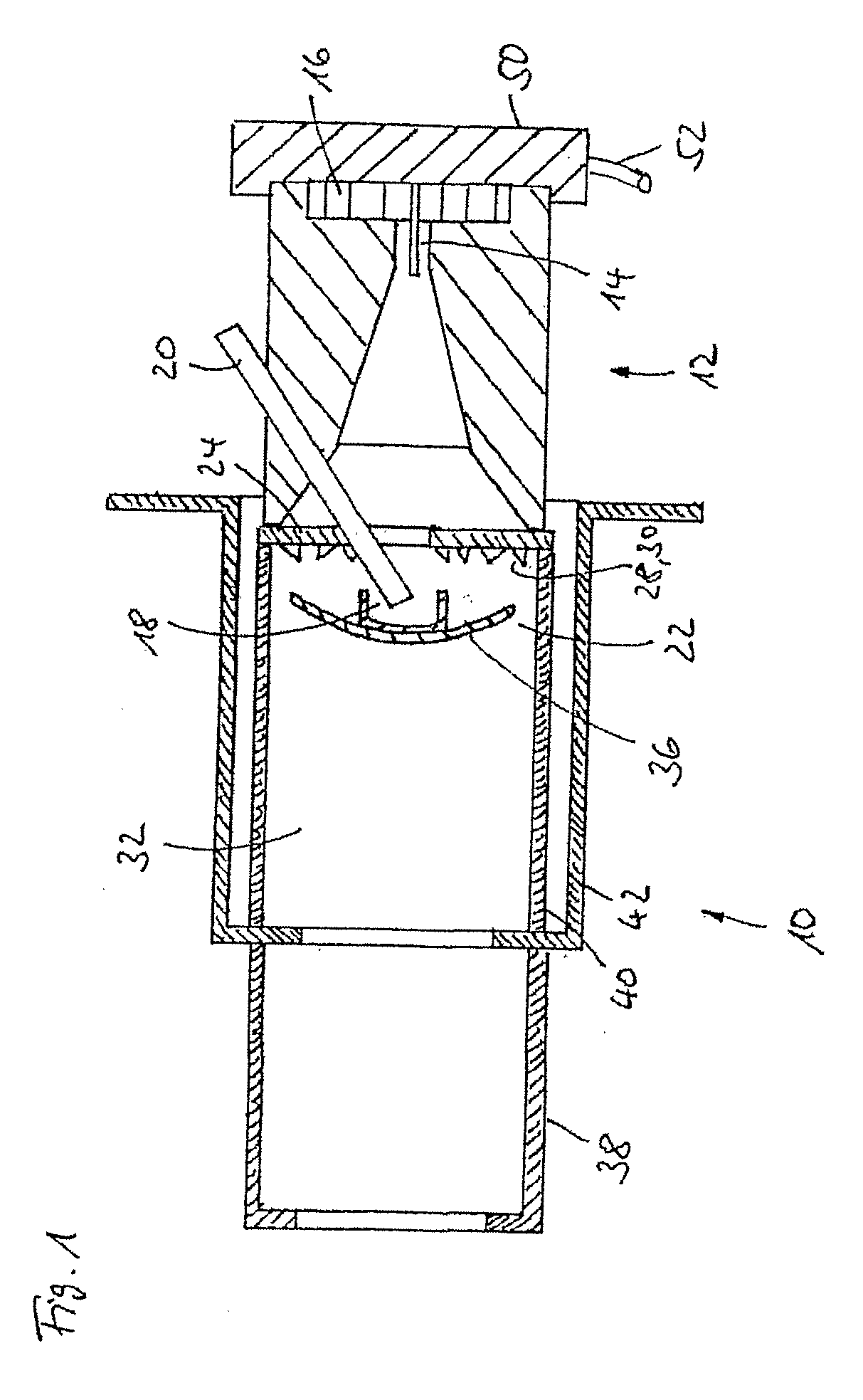
[0029]FIG. 1 shows a sectional view of a burner 10 of the invention. The burner 10 has a nozzle 12 which is securely joined to the heat shield 24. The heat shield 24, together with a burner pipe 40 which is connected to the heat shield 24, defines a combustion chamber 22. The combustion chamber pipe 40 is surrounded by an outer pipe 42 which forms the burner flange. A flame tube 38 is attached to this outer pipe 42. The connections between the heat shield 24 and the combustion chamber pipe 40 or between the combustion chamber pipe 40, the outer pipe 42 and the flame tube 38 are generally welded connections. On the fuel nozzle 12, there is a fuel supply 50 which has a metal pipe 52 for supply of fuel and a fuel needle 14 for injection of fuel into the combustion chamber 22. Furthermore, in the region of the fuel nozzle 16, there are channels...


PUM


Abstract

A burner for a heater, especially for motor vehicles, has an essentially axially symmetrical combustion chamber, a burner nozzle for supply and atomization of fuel, a fuel needle for supplying fuel to the combustion chamber, a combustion air supply for supplying combustion air to the combustion chamber, a starting zone in which ignition of the fuel to start the burner takes place, a heat shield between the burner nozzle and the combustion chamber, the heat shield having openings for supplying secondary air to the combustion chamber, and a baffle plate located in the combustion chamber. By choosing the inside diameter of the fuel needle, the exit speed of the fuel is predetermined such that, during the starting phase of the burner; fuel in essentially unatomized form reaches the starting zone. The openings have air guide elements, and the baffle plate has a defined curvature in the axial direction.

Description

BACKGROUND OF THE INVENTION[0001]1. Field of Invention[0002]The invention relates to a burner for a heater, especially for use in motor vehicles, with an essentially axially symmetrical combustion chamber, a burner nozzle for supply and atomization of fuel, which has a fuel needle for supplying fuel to the combustion chamber and a combustion air supply for supplying combustion air to the combustion chamber, a starting zone in which ignition of the fuel to start the burner takes place, a heat shield between the burner nozzle and the combustion chamber, the heat shield having openings for supplying secondary air to the combustion chamber, and a baffle plate which is located in the combustion chamber.[0003]2. Description of Related Art[0004]Burners of the initially described type, which are also called atomization burners or spray burners, are used especially in auxiliary heaters and independent heaters for motor vehicles.[0005]There are numerous requirements for these burners, especia...

Claims


Application Information

Patent Timeline
IPC IPC(8): F23M9/06F23Q7/06
CPCF23D9/00F23D11/24F23D2900/11401F23D11/408F23D11/406F23D11/40
Inventor POEHNER, MICHAELWIDEMANN, FRIEDRICHWEBER, STEFFENSTEFFENS, JAN
Owner WEBASTO AG
Why Eureka
Try Eureka