Patient Selectable Joint Arthroplasty Devices and Surgical Tools

a patient-selected, joint technology, applied in the field of surgical templates, can solve the problems of serious physical deformity, debilitating, limited repair ability of cartilage, etc., and achieve the effect of improving or optimizing the position of the bone cu

Active Publication Date: 2009-09-03
CONFORMIS
View PDF103 Cites 450 Cited by
  • Summary
  • Abstract
  • Description
  • Claims
  • Application Information

AI Technical Summary

Benefits of technology

[0027]Other embodiments can include one or more of the following. The method can further include selecting one of the first and second templates based on at least one of ligament balancing and ligament tension. The method can also include attaching a third template to the selected template, the third template, including at least one guide for guiding a surgical instrument; positioning the first surface of the selected template onto the first joint surface; and guiding the surgical instrument using the at least one guide. The joint can be one of a knee joint, a hip joint, a shoulder joint, an elbow joint, a wrist joint, a finger joint, a toe joint, and an ankle joint.
[0028]Another embodiment is a system for articular repair that includes first and second templates having a first surface that conforms with, and substantially is a negative of, at least a portion of a distal femur. It also includes a second template that has a third surface that conforms with, and is substantially a negative of, a portion of the distal femur. The second template can include at least one guide for guiding a surgical instrument in making a cut on the distal femur, and an attachment mechanism for attaching the second template to the first template.
[0029]Other embodiments can include one or more of the following. The first or second templates can include a guide for making a vertical femoral cut. The second surface can be at least one of substantially flat, substantially concave, substantially convex, and matched to one of the tibia and the femur. At least one other template can have a first surface that conforms with, and substantially is a negative of, the at least a portion of the distal femur. Each of the other templates can be capable of attaching to the second template. The first template and each of the other templates can vary in thickness. At least a portion of the first surface can substantially conform to at least one of uncut subchondral bone, uncut cartilage, and uncut bone of a distal femur. At least a portion of the second surface can substantially conform to at least one of uncut subchondral bone, uncut cartilage, and uncut bone of a distal femur. At least a portion of the third surface can substantially conform to at least one of uncut subchondral bone, uncut cartilage, and uncut bone of a tibia. The attachment mechanism can include at least one of a snapfit, dovetail and a cross-pin. The attachment mechanism can allow for rotation relative to one of an anatomical and a biomechanical axis.
[0030]Another embodiment is a system for articular repair that includes a first template having a first surface and a second surface, the first surface substantially conforming to at least a portion of the distal femur. The first template includes a medial edge that corresponds to a predetermined location for a vertical femoral or tibial cut.
[0031]Other embodiments can have one or more of the following. A second template can have a third surface substantially conforming to at least a portion of the distal femur or tibial plateau. The second template can include at least one guide for guiding a surgical instrument. There can also be an attachment mechanism for attaching the second template to the first template. The first template can include a guide for guiding a surgical instrument. The medial edge can be adapted as a guide for making a vertical tibial or femoral cut. At least one other template can have a first surface and a second surface. The first surface can substantially conform to at least a portion of the tibial plateau. The first template and each of the other templates can vary in thickness. At least a portion of the first surface can substantially conforms to at least one of uncut subchondral bone, uncut cartilage, and uncut bone.
[0032]Some embodiments can be used for a partial joint replacement, a total joint replacement, a partial joint resurfacing and a total joint resurfacing. Templates can vary in thickness or curvatures or can be made available in multiple different thicknesses or curvatures. The thickness of the other template can be selected to improve or optimize the position of a bone cut for ligament balancing.

Problems solved by technology

Adult cartilage has a limited ability of repair; thus, damage to cartilage produced by disease, such as rheumatoid and / or osteoarthritis, or trauma can lead to serious physical deformity and debilitation.

Method used


Image

  • Patient Selectable Joint Arthroplasty Devices and Surgical Tools
  • Patient Selectable Joint Arthroplasty Devices and Surgical Tools
  • Patient Selectable Joint Arthroplasty Devices and Surgical Tools

Examples


example 1

Unicompartmental Knee Resurfacing Using Patient-Specific Implants and Instrumentation

[0203]An exemplary surgical technique for use in implanting a novel partial knee resurfacing UKA using customized, single-use instrumentation is described below, in accordance with one embodiment of the invention.

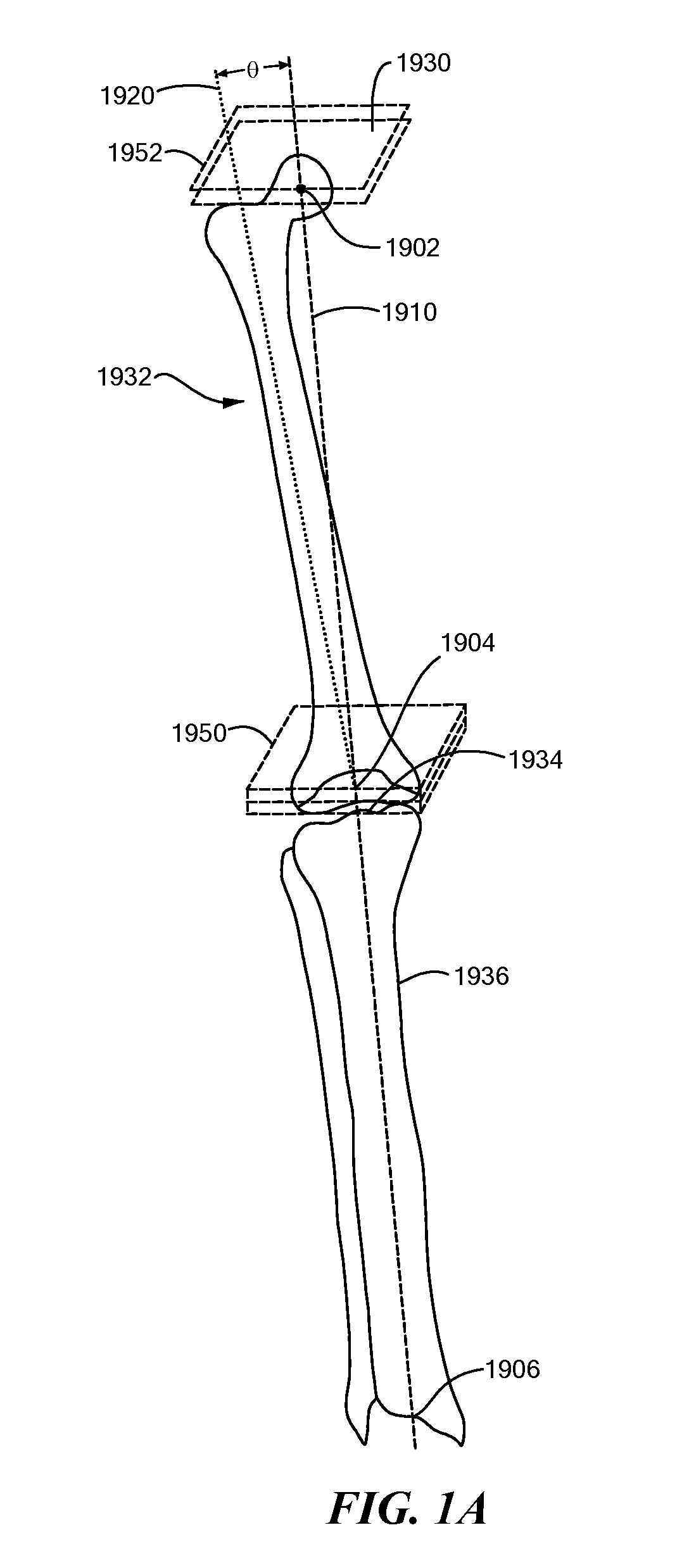
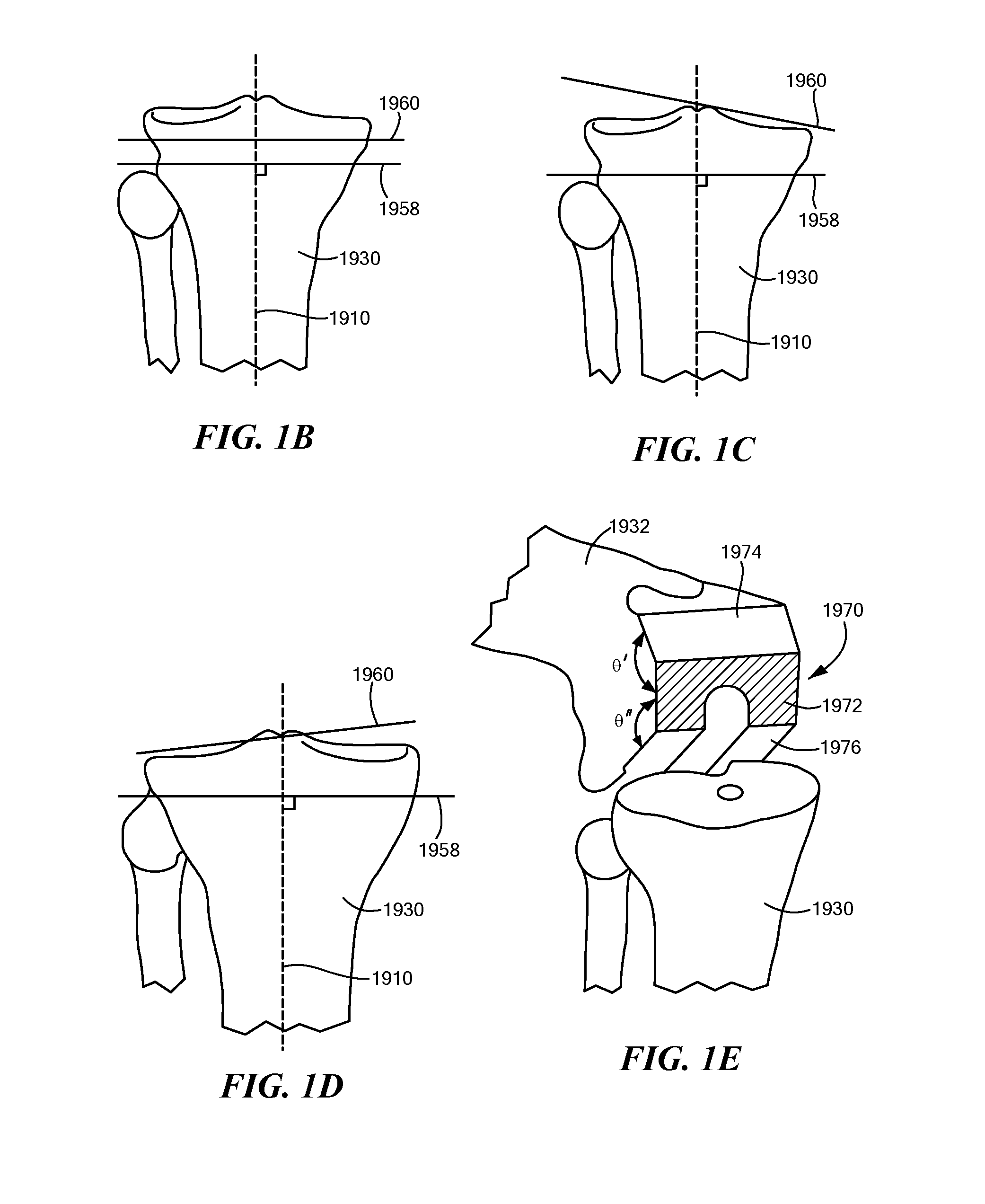
[0204]CT scans of a patient's knee and partial scans of the hip and ankle are utilized to create patient-specific implants and instrumentation. Based on the CT images, the knee anatomy is digitally recreated, the surface topography of the femur and tibia are mapped, and axis deformity is corrected. The same data is used to create cutting and placement guides that are pre-sized and pre-navigated to work with the patient's anatomy and custom implants.

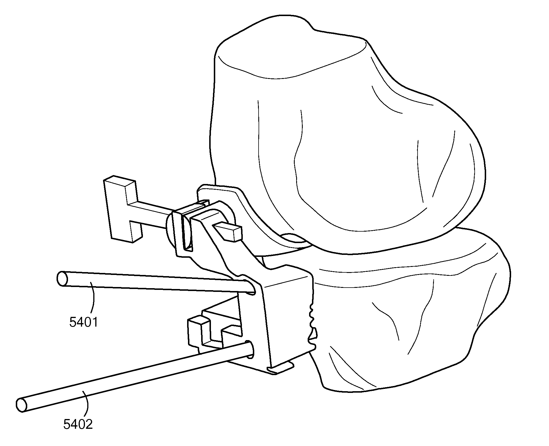
[0205]A kit may be provided with the resurfacing implants and disposable instrumentation in a single sterile tray, as shown in FIG. 31, in accordance with one embodiment of the invention. The various instruments in the kit may be patient-specific...


PUM


Abstract

Disclosed herein are tools for repairing articular surfaces repair materials and for repairing an articular surface. The surgical tools are designed to be customizable or highly selectable by patient to increase the speed, accuracy and simplicity of performing total or partial arthroplasty.

Description

CROSS-REFERENCE TO RELATED APPLICATIONS[0001]This application claims priority from U.S. Provisional Application Ser. No. 61 / 034,048, filed Mar. 5, 2008, entitled “Patient Selectable Joint Arthroplasty Devices and Surgical Tools,” and U.S. Provisional Application Ser. No. 61 / 052,430, filed May 12, 2008, entitled “Patient Selectable Joint Arthroplasty Devices and Surgical Tools.”[0002]This application is also a continuation in part of U.S. Ser. No. 11 / 671,745, filed Feb. 6, 2007, entitled “Patient Selectable Joint Arthroplasty Devices and Surgical Tools”, which in turn claims the benefit of U.S. Ser. No. 60 / 765,592 entitled “SURGICAL TOOLS FOR PERFORMING JOINT ARTHROPLASTY” filed Feb. 6, 2006; U.S. Ser. No. 60 / 785,168, entitled “SURGICAL TOOLS FOR PERFORMING JOINT ARTHROPLASTY” filed Mar. 23, 2006; and U.S. Ser. No. 60 / 788,339, entitled “SURGICAL TOOLS FOR PERFORMING JOINT ARTHROPLASTY” filed Mar. 31, 2006.[0003]U.S. Ser. No. 11 / 671,745 is also a continuation-in-part of U.S. Ser. No. ...

Claims


Application Information

Patent Timeline
Patent Type & Authority Applications(United States)
IPC IPC(8): A61B17/58
CPCA61B5/103A61B5/4514A61B5/4528A61B17/155A61B17/17A61B17/1764A61B19/50A61B19/5244A61B17/157A61B34/20A61B34/10B33Y80/00A61B2034/108A61B2034/2065A61B17/158A61B17/1615A61B17/1659A61B17/1703A61B17/1746A61B17/175A61B17/1767A61B2017/00526
Inventor BOJARSKI, RAYMONDFITZ, WOLFGANGLANG, PHILIPP
Owner CONFORMIS
Why Eureka
Try Eureka