Humidification of respiratory gases

a technology of respiratory gases and humidification systems, which is applied in the field of humidification of respiratory gases, can solve the problems of limited humidification systems used with cpap devices for home use, inconvenient home use, and inconvenient use of cpap devices, and achieves the disadvantages of commonly employed control techniques described abov

Active Publication Date: 2009-09-10
RESMED LTD
View PDF110 Cites 240 Cited by
  • Summary
  • Abstract
  • Description
  • Claims
  • Application Information

AI Technical Summary

Benefits of technology

[0031]According to yet another sample embodiment, a humidifier for a respiratory apparatus for delivering a humidified flow of breathable gas to a patient comprises a humidifier chamber configured to store a supply of water to humidify the flow of breathable gas, the humidifier chamber comprising a first heating element configured to heat the supply of water; an absolute humidity sensor to detect a...

Problems solved by technology

Humidification systems used with CPAP devices for home use have been limited due to pricing constraints, and by the need to maintain the systems small and lightweight, with a comfortable hose and mask, and a low complexity for untrained users.
The cost, size, weight and discomfort of these systems have not been suited to home use.
These temperature variations cause the commonly employed control techniques described above to suffer disadvantages.
The formation of large quantities of wa...

Method used


Image

  • Humidification of respiratory gases
  • Humidification of respiratory gases
  • Humidification of respiratory gases

Examples


example 1

Adjustment to Change in Ambient Temperature with Mask Temperature Controlled

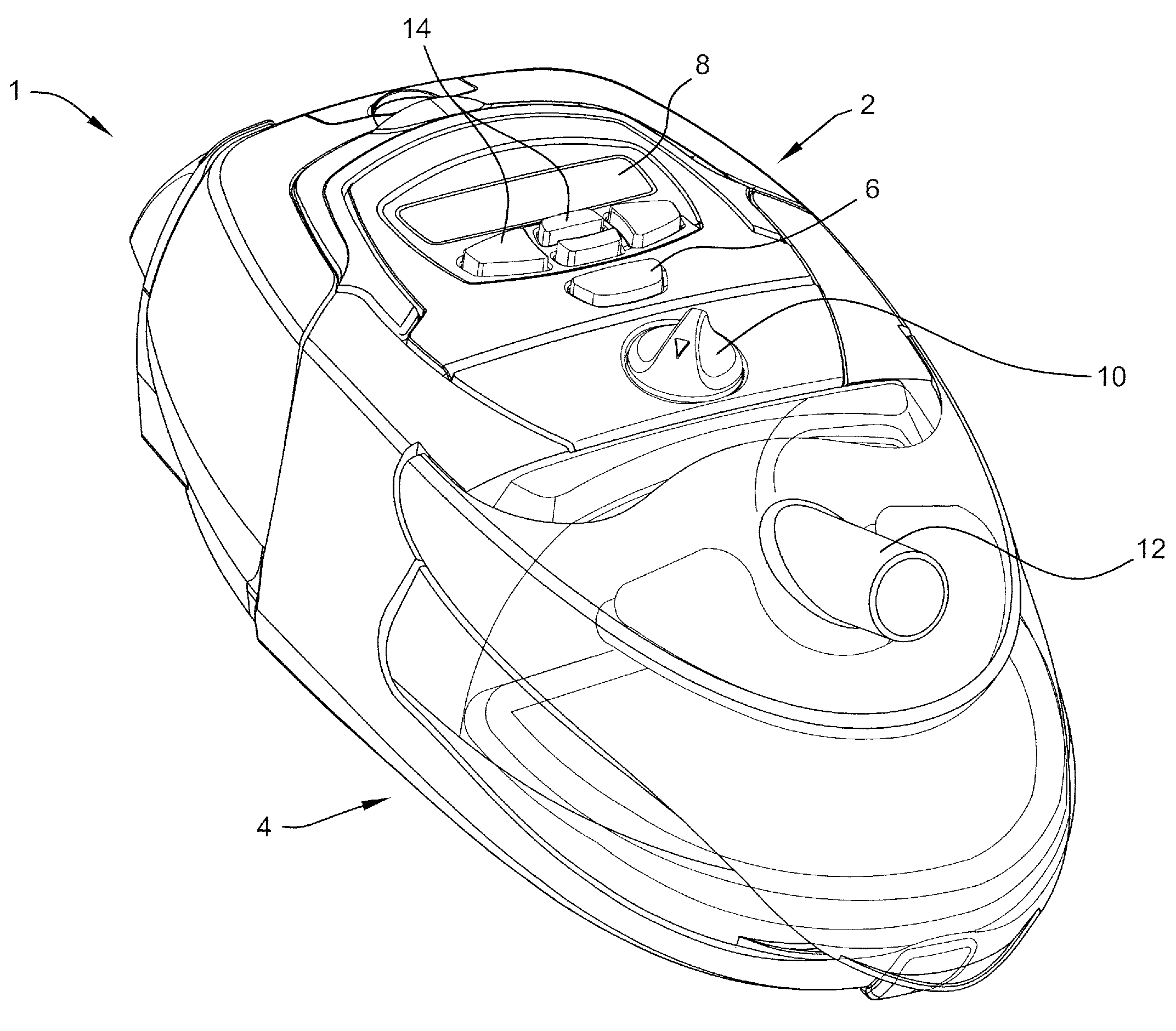
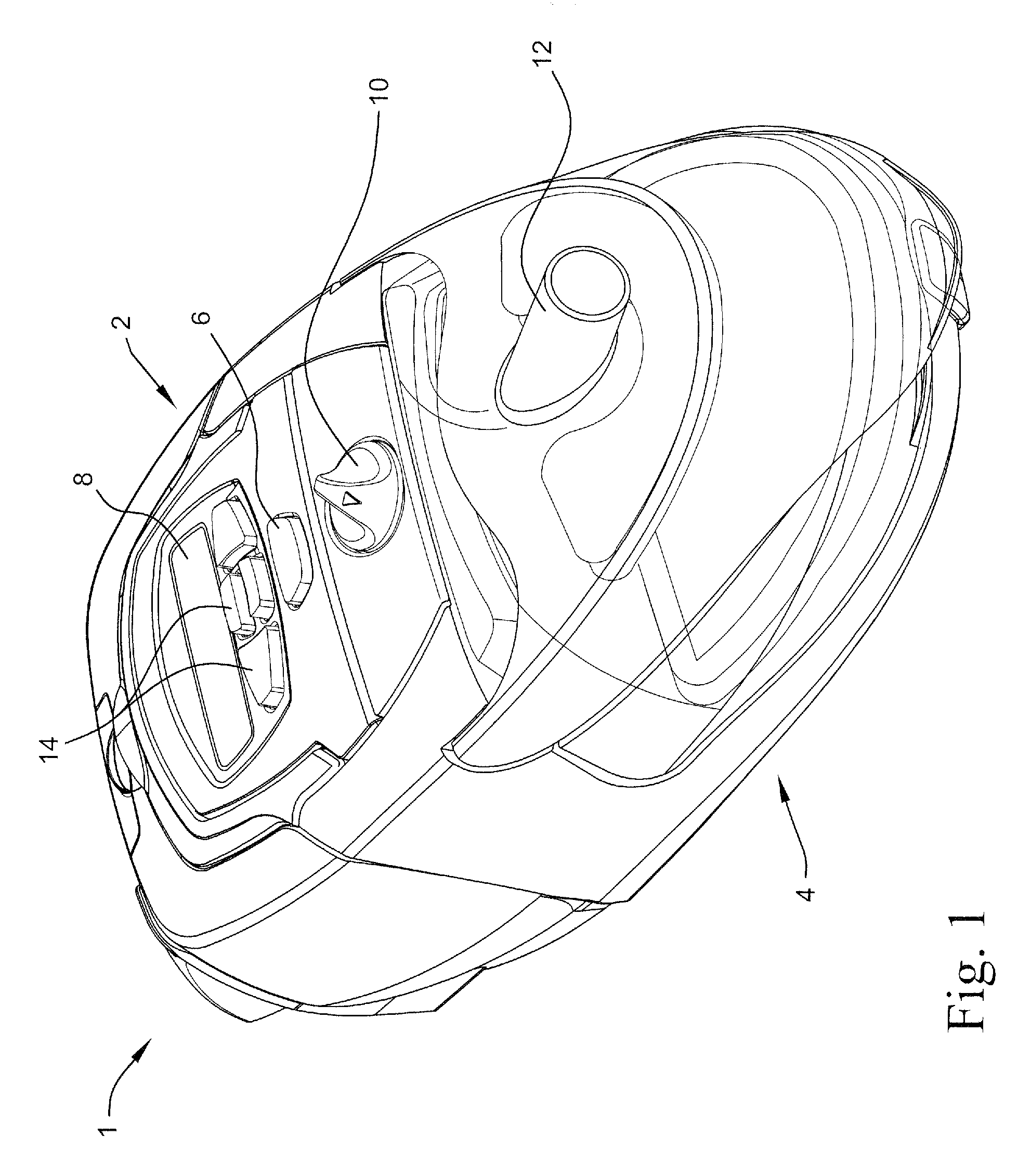
[0092]In this example, the system of FIG. 6 is set to deliver saturated air to the mask at 30° C. The temperature may be set by the patient, or clinician, by use of the control buttons 14 of the flow generator 2 and / or the control knob 10 of the humidifier 4. The absolute humidity of the ambient air is 10 mg / L, which does not change as the temperature of the ambient air changes, for example in the patient's bedroom, during the patient's sleep. As shown in Table 1, the temperature of the water in the humidifier tub is adjusted to achieve 100% RH air at the patient interface.

TABLE 1AirHumidityHumidityWaterAirabsoluteAirTemperatureof airof airtemperaturetemperaturehumidityrelativeHumidificationof airdelivereddelivereddeg C.deg C.(mg / L)humidityoutput mg / Ldelivered(mg / L)% RH64.9151080%20.73030.7100%64.9161075%21.03031.0100%64.7171071%20.93030.9100%64.5181066%20.93030.9100%64.3191062%20.73030.7100%64.320...

example 2

Adjustment to Change in Set Temperature at Patient Interface

[0096]Referring to Table 3 and FIG. 10, in this example, the system of FIG. 6 is controlled to deliver saturated air and the temperature at the patient interface is changed.

TABLE 3AirHumidityHumidityWaterAirabsoluteAirTemperatureof airof airtemperaturetemperaturehumidityrelativeHumidificationof airdelivereddelivereddeg C.deg C.(mg / L)humidityoutput mg / Ldelivered(mg / L)% RH5322.51050%10.62320.6100%54.622.51050%11.82421.8100%56.522.51050%13.42523.4100%5822.51050%14.62624.6100%59.622.51050%16.12726.1100%61.222.51050%17.62827.6100%62.822.51050%19.32929.3100%64.222.51050%20.83030.8100%65.822.51050%22.63132.6100%67.222.51050%24.23234.2100%68.722.51050%26.13336.1100%70.222.51050%28.03438.0100%71.722.51050%30.03540.0100%

[0097]The ambient air is assumed to be 22.5° C., the absolute humidity is 10 mg / L, and the relative humidity is 50%. The ambient air conditions are assumed not to change. The temperature of the water in the hu...

example 3

Adjustment to Change in Ambient Humidity

[0099]The system of FIG. 6 may also be configured to adjust for changes in ambient humidity. For example, signals from the sensors 50, 52 may be provided to the controller(s) 40 and / or 44 to periodically or continuously calculate the absolute humidity of the ambient air. As shown in Table 4 and FIG. 11, the temperature of the ambient air is maintained relatively constant, for example 22.5° C., but the absolute humidity changes throughout the course of the patient's sleep cycle.

TABLE 4AirHumidityHumidityWaterAirabsoluteAirTemperatureof airof airtemperaturetemperaturehumidityrelativeHumidificationof airdelivereddelivereddeg C.deg C.(mg / L)humidityoutput mg / Ldelivered(mg / L)% RH68.522.5420%26.83030.8100%6822.5525%26.03031.0100%67.222.5630%24.93030.9100%66.522.5735%23.93030.9100%65.822.5840%22.93030.9100%6522.5945%21.83030.8100%64.222.51050%20.83030.8100%63.522.51155%19.93030.9100%62.822.51260%19.03031.0100%6222.51365%18.03031.0100%6122.5147...


PUM


Abstract

A humidifier for a respiratory apparatus for delivering a humidified flow of breathable gas to a patient includes a humidifier chamber configured to store a supply of water to humidify the flow of breathable gas, the humidifier chamber comprising a first heating element configured to heat the supply of water; a relative humidity sensor to detect a relative humidity of ambient air and generate signals indicative of the ambient relative humidity; a first temperature sensor to detect a temperature of ambient air and generate signals indicative of the ambient temperature; and a controller configured to determine an absolute humidity of the ambient air from the signals generated by the relative humidity sensor and the first temperature sensor and to control the first heating element to provide a predetermined relative humidity to the flow of breathable gas. A method of humidifying a flow of breathable gas to be provided to a patient includes determining an absolute humidity of ambient air used to form the flow of breathable gas; and controlling a temperature of a supply of water that humidifies the flow of breathable gas to provide a predetermined absolute humidity corresponding to a predetermined temperature and a predetermined relative humidity of the flow to be delivered to the patient.

Description

CROSS REFERENCE TO RELATED APPLICATIONS[0001]This application claims priority to U.S. Applications 61 / 034,318, filed Mar. 6, 2008, 61 / 042,112, filed Apr. 3, 2008, and 61 / 084,366, filed Jul. 29, 2008, the entire contents of each being incorporated herein by reference.FIELD OF THE INVENTION[0002]The present invention relates to systems and methods to control the humidity of breathable gases used in all forms of respiratory apparatus ventilation systems including invasive and non-invasive ventilation, Continuous Positive Airway Pressure (CPAP), Bi-Level therapy and treatment for sleep disordered breathing (SDB) conditions such as Obstructive Sleep Apnea (OSA), and for various other respiratory disorders and diseases.BACKGROUND OF THE INVENTION[0003]Respiratory apparatuses commonly have the ability to alter the humidity of the breathable gas in order to reduce drying of the patient's airway and consequent patient discomfort and associated complications. The use of a humidifier placed be...

Claims


Application Information

Patent Timeline
IPC IPC(8): A61M16/16
CPCA61M16/1075A61M16/16A61M2016/0039A61M2205/3358A61M2205/3365A61M16/161A61M2205/3653A61M2205/502A61M16/109A61M16/1095A61M2205/3368A61M16/026
Inventor SMITH, IAN MALCOLMBATH, ANDREW RODERICKROW, NATHAN JOHNVIRR, ALEXANDER
Owner RESMED LTD
Why Eureka
Try Eureka