Electric Rotating Machine and Hybrid Car Provided with the Same

Active Publication Date: 2009-09-10
HITACHI LTD
View PDF17 Cites 22 Cited by
  • Summary
  • Abstract
  • Description
  • Claims
  • Application Information

AI Technical Summary

Benefits of technology

[0009]Thus, the present invention provides an electric rotating machine capable of withstanding operations at high rotating speed wit

Problems solved by technology

However, an increased current increases heat generated by the electric rotating

Method used


Image

  • Electric Rotating Machine and Hybrid Car Provided with the Same
  • Electric Rotating Machine and Hybrid Car Provided with the Same
  • Electric Rotating Machine and Hybrid Car Provided with the Same

Examples


Embodiment Construction

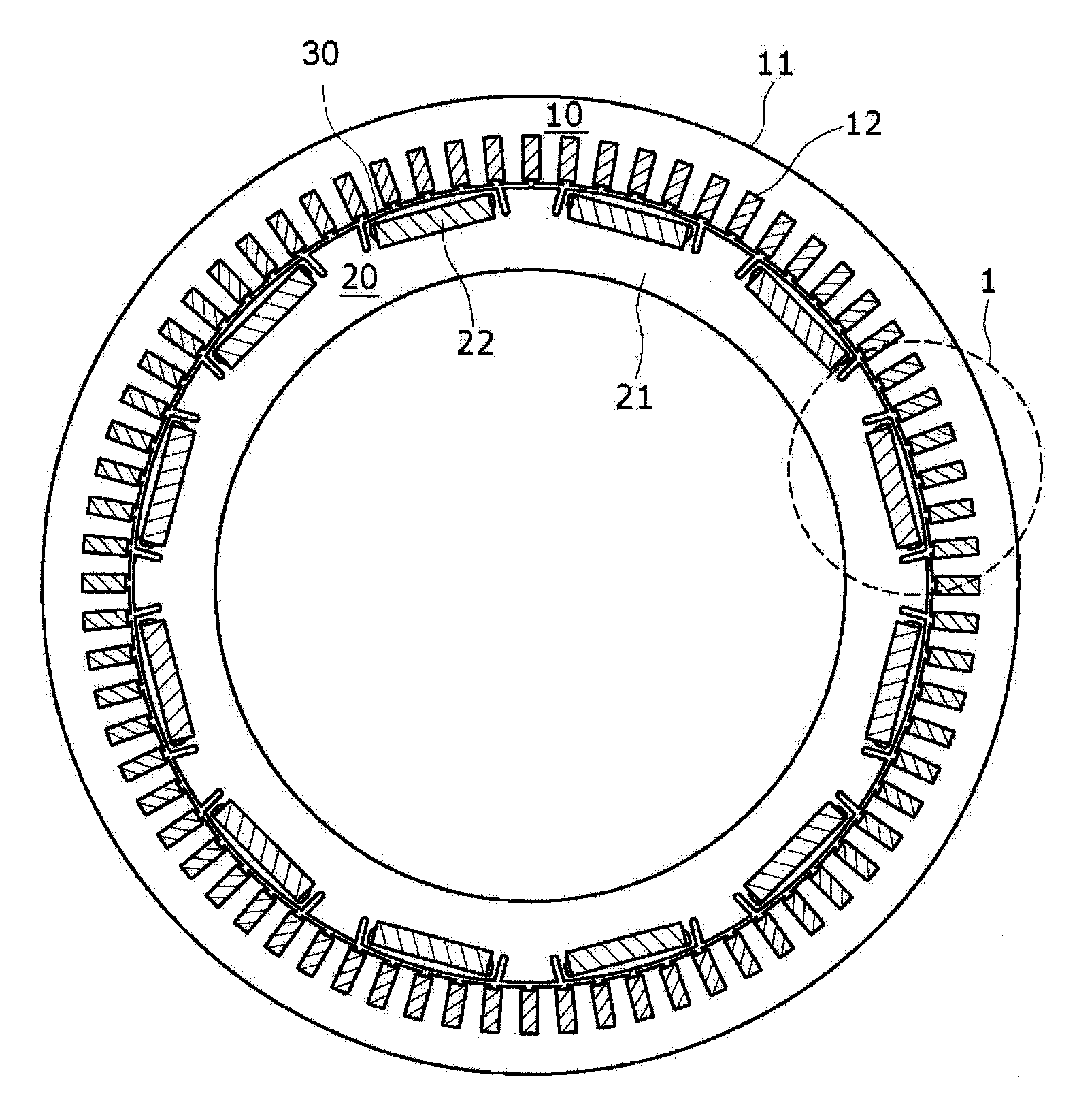
[0021]Preferably, a permanent-magnet-type electric rotating machine has a rotor including a rotor core in which compressive stress is intentionally induced to reduce tensile stress that may be induced in the rotor core when the rotor rotates. Preferably, the absolute value of the compressive stress is equal to that of the tensile stress.

[0022]More specifically, the rotor core is provided with magnet holding cavities respectively holding permanent magnets therein, nonmagnetic parts disposed on the opposite sides, respectively, of each magnet holding cavity, and slits formed in the circumference of the rotor core on the outer side of the nonmagnetic parts in a depth greater than the distance between the circumference of the rotor and each nonmagnetic part. Preferably, the bottom of the slit is nearer to the center of the magnetic pole of the rotor than the open end of the slit. Preferably, the thickness along the circumference of the rotor of a part of the rotor core, extending betwee...


PUM


Abstract

An electric rotating machine includes a stator, a rotor inserted in a bore of the stator such that an air gap is formed between the stator and the rotor, and a plurality of permanent magnets embedded in a peripheral portion of the rotor core of the rotor in a circumferential arrangement. Slits are formed in portions of the rotor core each extending between the adjacent magnetic poles. Compressive stress is induced in portions of the rotor core each extending between the slit and the permanent magnet when stress is induced in the portion of the stator core extending between the slit and the permanent magnet by centrifugal force produced when the rotor rotates and acting on the permanent magnet and a pole piece covering the permanent magnet.

Description

BACKGROUND OF THE INVENTION[0001]The present invention relates to an electric rotating machine and a hybrid car provided with the same.[0002]There has been a demand for an electric rotating machine, more specifically, a permanent-magnet-type electric rotating machine for driving a vehicle, including an inverter for controlling the same having a reduced size and capable of providing an increased output power. There has been a demand particularly for a permanent-magnet-type electric rotating machine capable of producing high torque at low operating speeds and of providing high output power at high rotating speeds. Therefore, the conventional permanent-magnet-type electric rotating machine is an embedded permanent-magnet-type electric rotating machine with salient poles using low field magnets for high-speed rotation and capable of using reluctance torque. See, for example, JP-A 1998-126985.[0003]A rotor core on the side of a permanent-magnet stator and a rotor core on the side of the ...

Claims


Application Information

Patent Timeline
IPC IPC(8): H02K1/27B60L50/15B60L50/16
CPCB60K6/448Y02T10/7077B60L11/123B60L11/14B60L15/007B60L2220/14B60L2220/18B60L2260/28B60L2270/145H02K1/276Y02T10/6217Y02T10/6243Y02T10/6265Y02T10/641B60K6/52B60L50/61B60L50/16Y02T10/62Y02T10/64Y02T10/7072Y02T10/70
Inventor SAITO, YASUYUKIGOTO, TSUYOSHIHINO, NORIAKIHOSHINO, KATSUHIRO
Owner HITACHI LTD
Why Eureka
Try Eureka