Control device for hybrid vehicle

a control device and hybrid technology, applied in the direction of vehicle sub-unit features, vehicle dynamo-electric gear control, transportation and packaging, etc., can solve the problems of increasing the slipping speed of the vehicle, reducing the rotation speed of the pump wheel of the hydraulic power transmission, and the electric motor may not be output satisfactorily

Inactive Publication Date: 2015-03-05
TOYOTA JIDOSHA KK
View PDF0 Cites 22 Cited by
  • Summary
  • Abstract
  • Description
  • Claims
  • Application Information

AI Technical Summary

Benefits of technology

[0006]In such a hybrid vehicle, in order to prevent slipping of the vehicle which occurs at the time of changing an applied pressure from a brake pedal to an accelerator pedal to start the vehicle in stop on a slope having a road surface gradient, a state where a torque is transmitted to an axle and driving wheels is set up by causing the electric motor to rotate in advance. However, when the road surface gradient is relatively large and a pressure cannot be applied to the accelerator pedal just after the brake pedal is released, a slipping speed of the

Problems solved by technology

However, when the road surface gradient is relatively large and a pressure cannot be applied to the accelerator pedal just after the brake pedal is released, a slipping speed of the vehicle increases and the rotation speed of a pump wheel

Method used


Image

  • Control device for hybrid vehicle
  • Control device for hybrid vehicle
  • Control device for hybrid vehicle

Examples


Embodiment Construction

[0022]Hereinafter, an embodiment of the present invention will be described in detail with reference to the accompanying drawings. In the following embodiment, the drawings are appropriately simplified or deformed, and the dimensional ratios and the shapes of the constituents thereof are not accurately drawn.

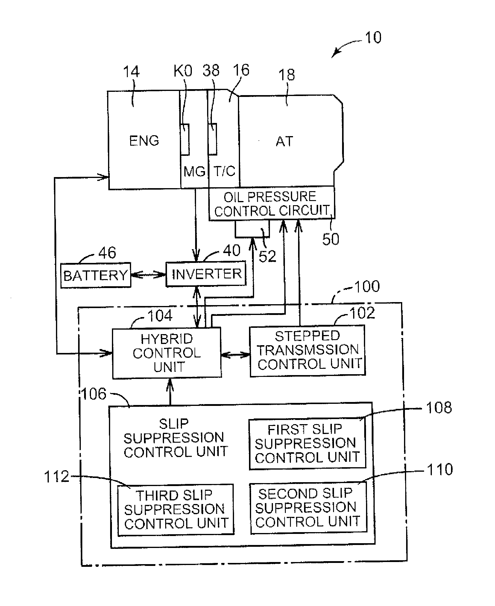
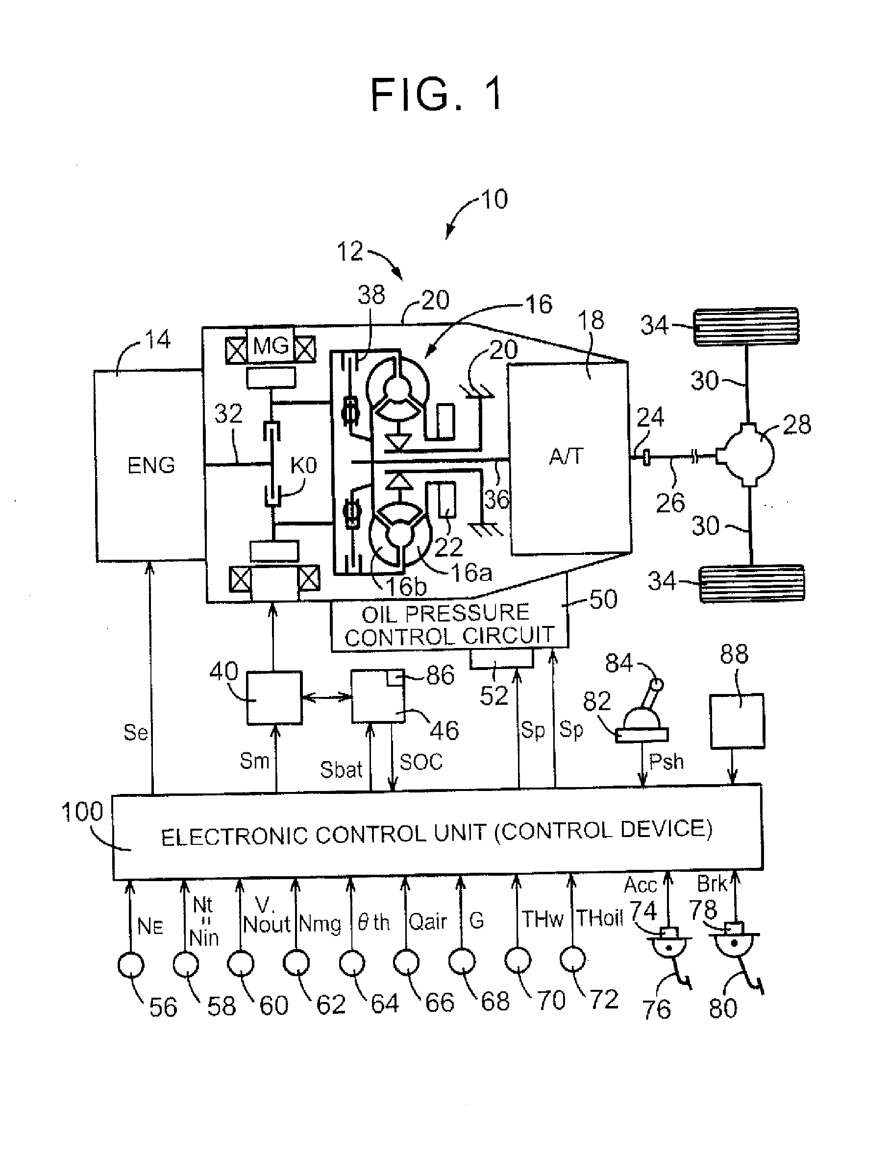
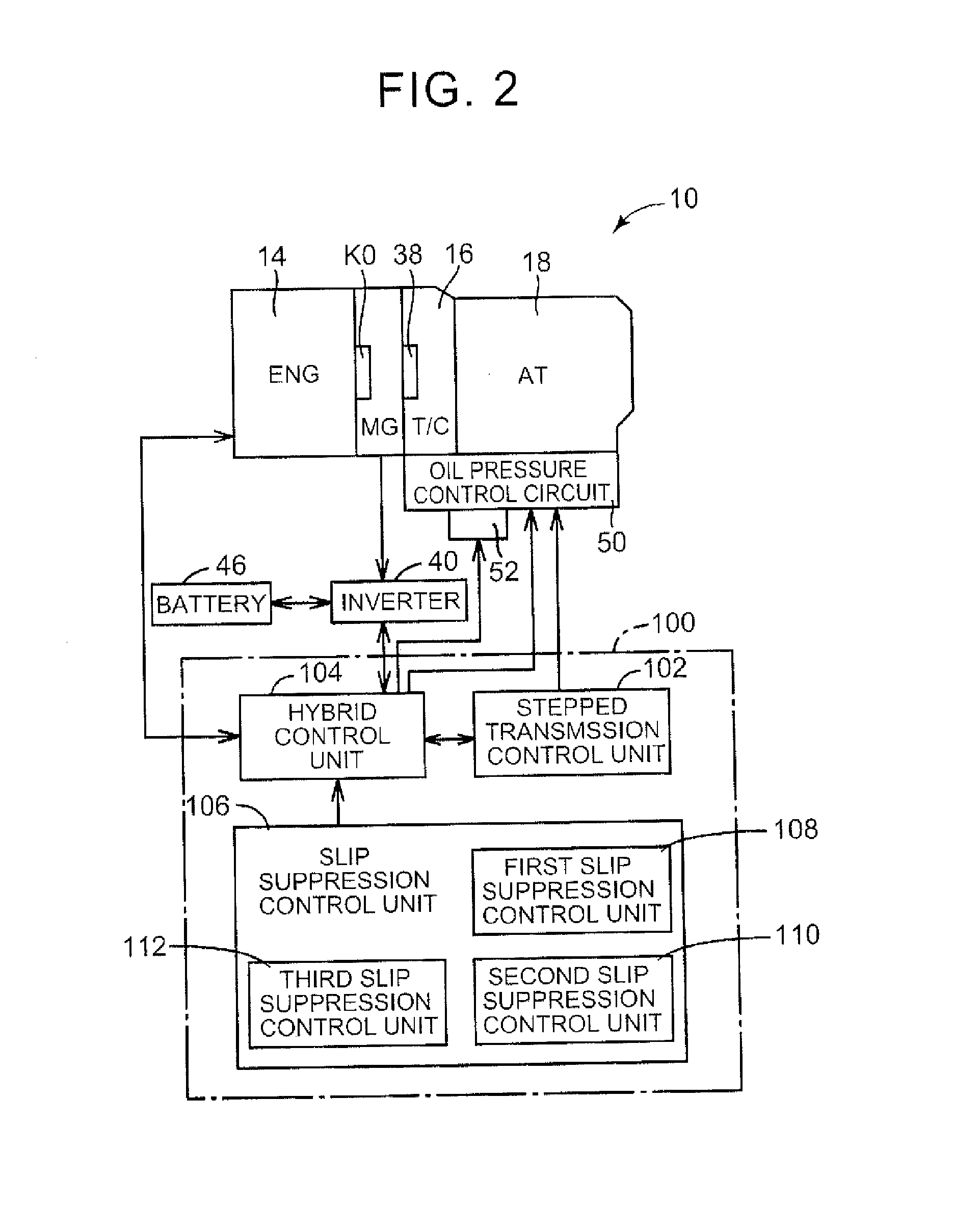
[0023]FIG. 1 is a diagram illustrating a schematic configuration of a power transmission path from an engine 14 and an electric motor MG to driving wheels 34, an engine 14 and an electric motor MG constituting a hybrid vehicle 10 (hereinafter, referred to as vehicle 10) to which the present invention is appropriately applied. FIG. 1 is also a diagram illustrating principal parts of a control system provided to the vehicle 10 for an output control of the engine 14 serving as a running drive source, a transmission control of an automatic transmission 18, a drive control of the electric motor MG, and the like.

[0024]In FIG. 1, a vehicle power transmission 12 (hereinafter, referred t...


PUM


Abstract

In a first slip suppression control by a first slip suppression control unit when a vehicle stops on a slope, an electronic control unit controls an output torque of an electric motor so that a rotation speed of an input rotation member of a hydraulic power transmission reaches a predetermined target rotation speed during stopping of an engine. The electronic control unit starts the engine when the output torque of the electric motor is greater than a predetermined torque. Accordingly, when the output torque of the electric motor at a rotation speed under a slip suppression control is insufficient, the output torque of the engine can be used and thus a locked state of the electric motor is appropriately prevented.

Description

INCORPORATION BY REFERENCE[0001]The disclosure of Japanese Patent Application No. 2013-177153 filed on Aug. 28, 2013 including the specification, drawings and abstract is incorporated herein by reference in its entirety.BACKGROUND OF THE INVENTION[0002]1. Field of the Invention[0003]The present invention relates to a control technique of suppressing slipping of a hybrid vehicle, which includes an engine and an electric motor as a drive source, on an uphill road.[0004]2. Description of Related Art[0005]A hybrid vehicle is well known which includes an engine, an electric motor, and a hydraulic power transmission that is disposed in a power transmission path between the engine and the electric motor and driving wheels so as to transmit dynamic power via a fluid. An example of such a hybrid vehicle is disclosed in Japanese Patent Application Publication No. 2000-308209 (JP 2000-308209 A).SUMMARY OF THE INVENTION[0006]In such a hybrid vehicle, in order to prevent slipping of the vehicle ...

Claims


Application Information

Patent Timeline
IPC IPC(8): B60W20/00B60W10/00B60W10/06B60W30/18B60W10/08
CPCB60W20/10B60W30/18009Y10S903/93B60W10/06B60W10/00B60W10/08B60W10/026B60W30/18027B60W30/18118B60W30/18172B60K2006/4825B60W2710/028B60W2710/083B60Y2400/426B60W2552/15Y02T10/62
Inventor HOSHIBA, TAKESHIUCHIDA, KENJIAOKI, TAKESHI
Owner TOYOTA JIDOSHA KK
Why Eureka
Try Eureka