
On-vehicle air conditioner

a technology for air conditioners and vehicles, applied in the field of on-vehicle air conditioners, can solve the problems of low waste heat of such vehicles, difficult use of refrigerant, and inability to use sub>2 /sub>as refrigeran

Inactive Publication Date: 2005-05-10
SANYO ELECTRIC CO LTD
View PDF11 Cites 24 Cited by
  • Summary
  • Abstract
  • Description
  • Claims
  • Application Information

AI Technical Summary

Benefits of technology

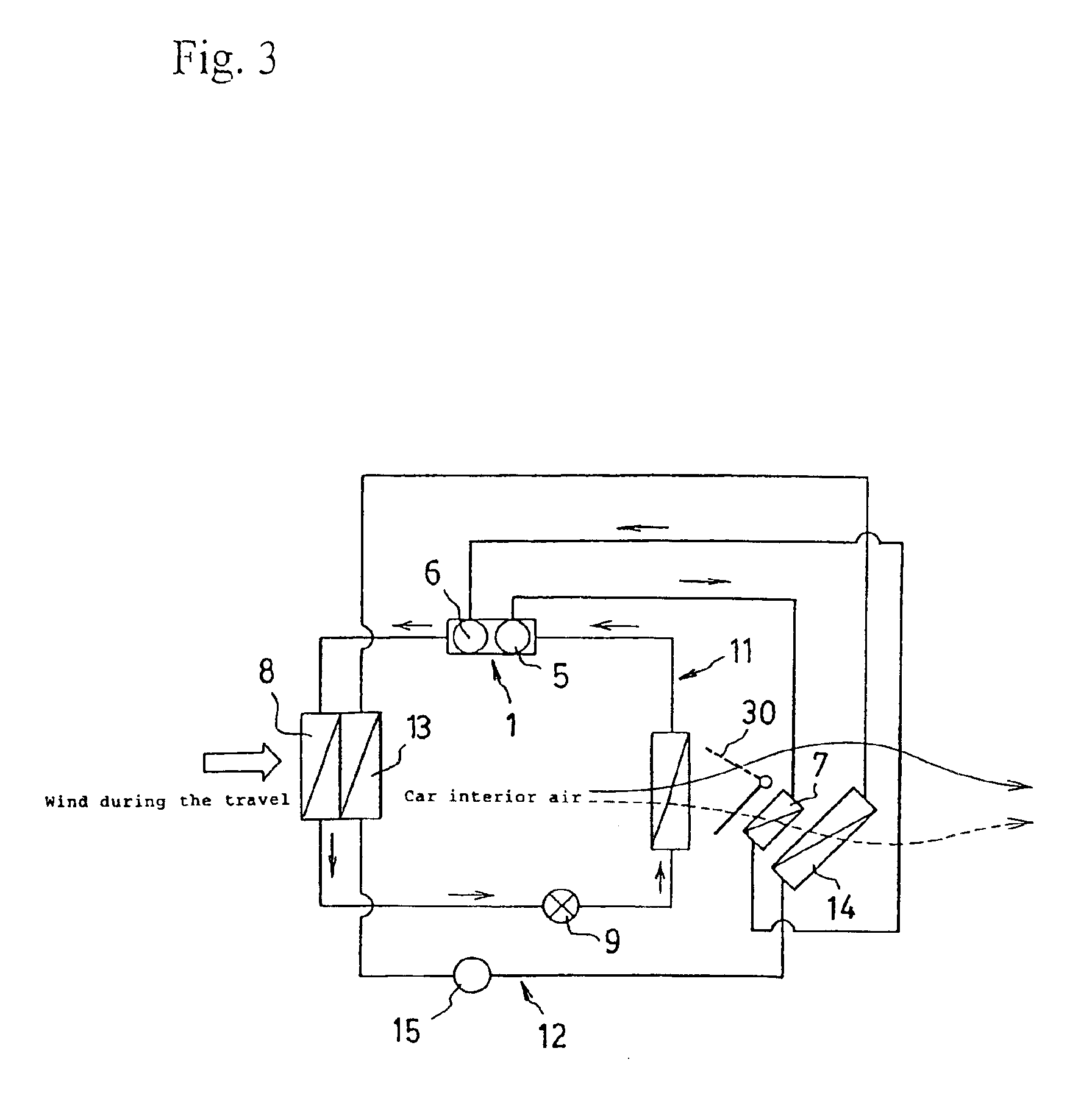
[0051]The on-vehicle air-conditioner of claim 1 of the present invention is an on-vehicle air-conditioner comprising a refrigeration circuit having a two-stage compression system compressor for cooling the refrigerant compressed in the first stage by a refrigerant heat exchanger, and compressing further the chilled refrigerant in the second stage before discharging, and an evaporator installed in a way to exchange heat with the car interior air, a cooling water circuit provided with a cooling water car interior heat exchanger for heating, where the engine cooling water circulates, installed in a way to exchange heat with the car interior air, and a damper apparatus for controlling the air course of whether or not passing the car interior air through the evaporator and / or cooling water car interior heat exchanger for heating, wherein the refrigerant heat exchanger is installed in a way to exchange heat with the car interior air, allowing to use for car interior heating together with the cooling water car interior heat exchanger for heating, whereby, the power necessary for driving the two-stage compression system compressor and a high efficiency driving can be realized by reducing the refrigerant temperature even for vehicles of low waste heat, such as hybrid cars taking electricity and gasoline as energy source, idle stop coping cars or battery cars taking only electricity as energy source, or other vehicles, and at the same time, during the cooling for instance, a satisfactory cooling can be realized by preventing the air passing through the refrigerant heat exchanger and cooling water car interior heat exchanger for heating from being sent into the vehicle, and during the heating, a satisfactory heating can be realized by sending the air passing through the refrigerant heat exchanger and cooling water car interior heat exchanger for heating into the vehicle, and during the dehumidification, a satisfactory dehumidification / temperature control can be realized by dehumidifying the car interior air through heat exchange by the evaporator of the refrigerant heat exchanger and, thereafter, sending the air to the refrigerant heat exchanger for heat exchange and then into the vehicle, or otherwise allowing to expect the improvement of efficiency during the heating, cooling and dehumidification or other remarkable effects can be offered. The on-vehicle air-conditioner of claim 2 of the present invention, using CO2 as refrigerant, has the same effect of the on-vehicle air-conditioner of claim 1, and moreover, has a remarkable effect of imposing less load to the environment. Being free from ozone layer destruction effect, combustibility or toxicity and, furthermore, extremely friendly to the environment as Global Warming Potential (GWP) is 1, and in addition, economical.
[0052]The industrial use value thereof is considerably important, because problems of the prior art can be resolved, and cooling, heating, dehumidification or others can be performed efficiently even for vehicles of low waste heat, such as hybrid cars taking electricity and gasoline as energy source, idle stop coping cars or battery cars taking only electricity as energy source, or other vehicles, by cooling by loading a refrigeration circuit, using for example CO2 refrigerant, and provided with an electrically driven two-stage system compressor, and at the same time, installing a refrigerant heat exchanger for cooling the refrigerant compressed in the first stage in a way to exchange heat with the car interior air, and using conveniently also for heating together with the heat of the cooling water for cooling the engine.

Problems solved by technology

There, refrigerants not containing chlorine group, for example, alternative refrigerants such as difluoromethane (HFC-32, R32, boiling point −52° C.) or others have been proposed; however, they ended up by being included in gases to be regulated by The 3rd Session of the Conference of the Parties to the United Nations Framework Convention on Climate Change, Kyoto, 1997, because Global Warming Potential (GWP) is 1300 to 1900, and their use comes to be difficult.
Nonetheless, in case of applying CO2 refrigerant to a refrigeration circuit, as a high operation pressure equal or superior to 3 times (for instance, 10 megapascals) compared to the refrigerant for air-conditioner of the prior art is required, there is a problem of closness of the compression chamber in the single stage compression system compressor structure of the prior art, and for example, it can only compress to the level of 6 megapascals, and there was a problem that CO2 could not be used as refrigerant.
Whatsoever, the waste heat of such vehicles is low, and there was a problem that a sufficient heating could not be performed.

Method used


Image

  • On-vehicle air conditioner
  • On-vehicle air conditioner
  • On-vehicle air conditioner

Examples


Embodiment Construction

[0024]Now, embodiments of the present invention are described in detail using drawings.

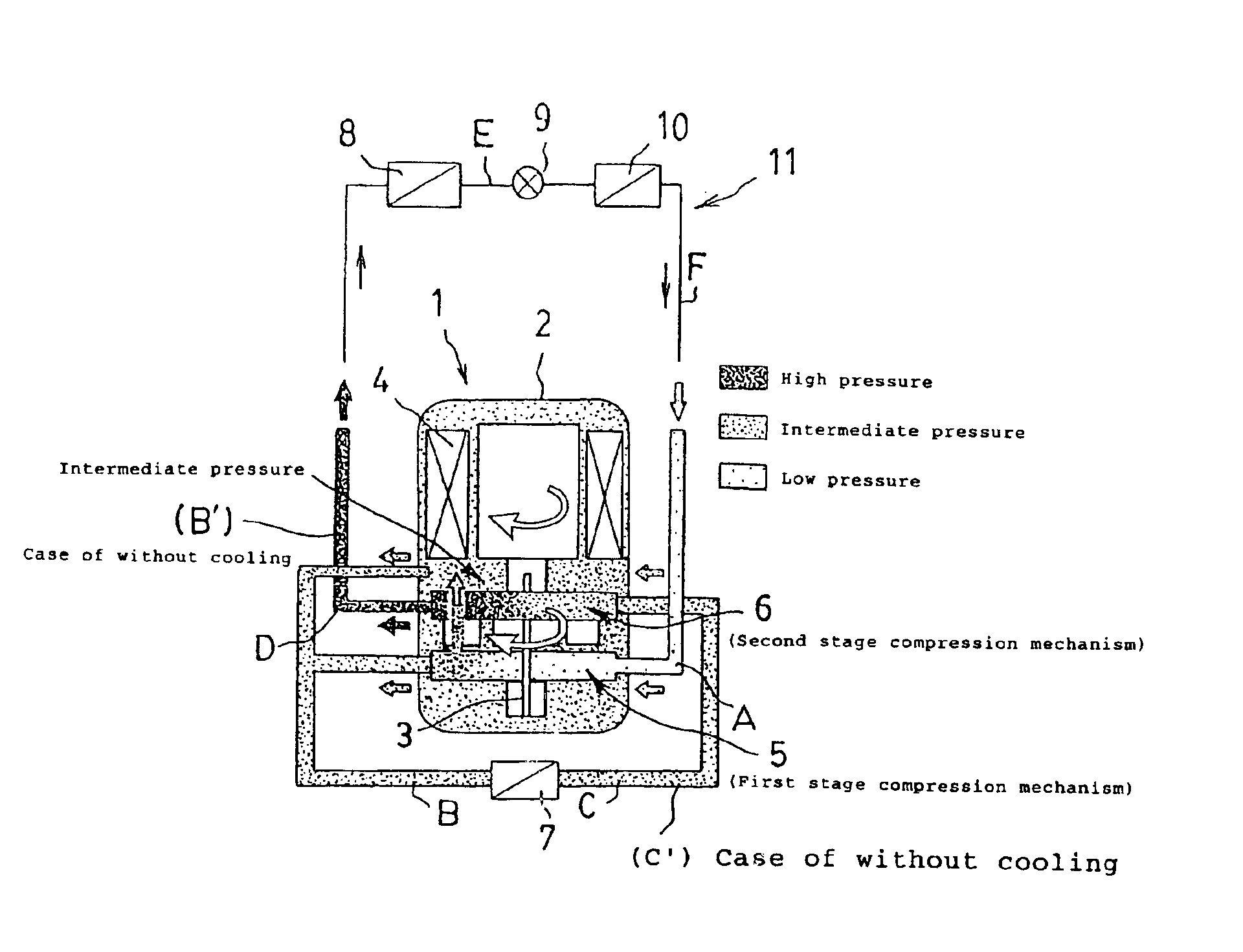
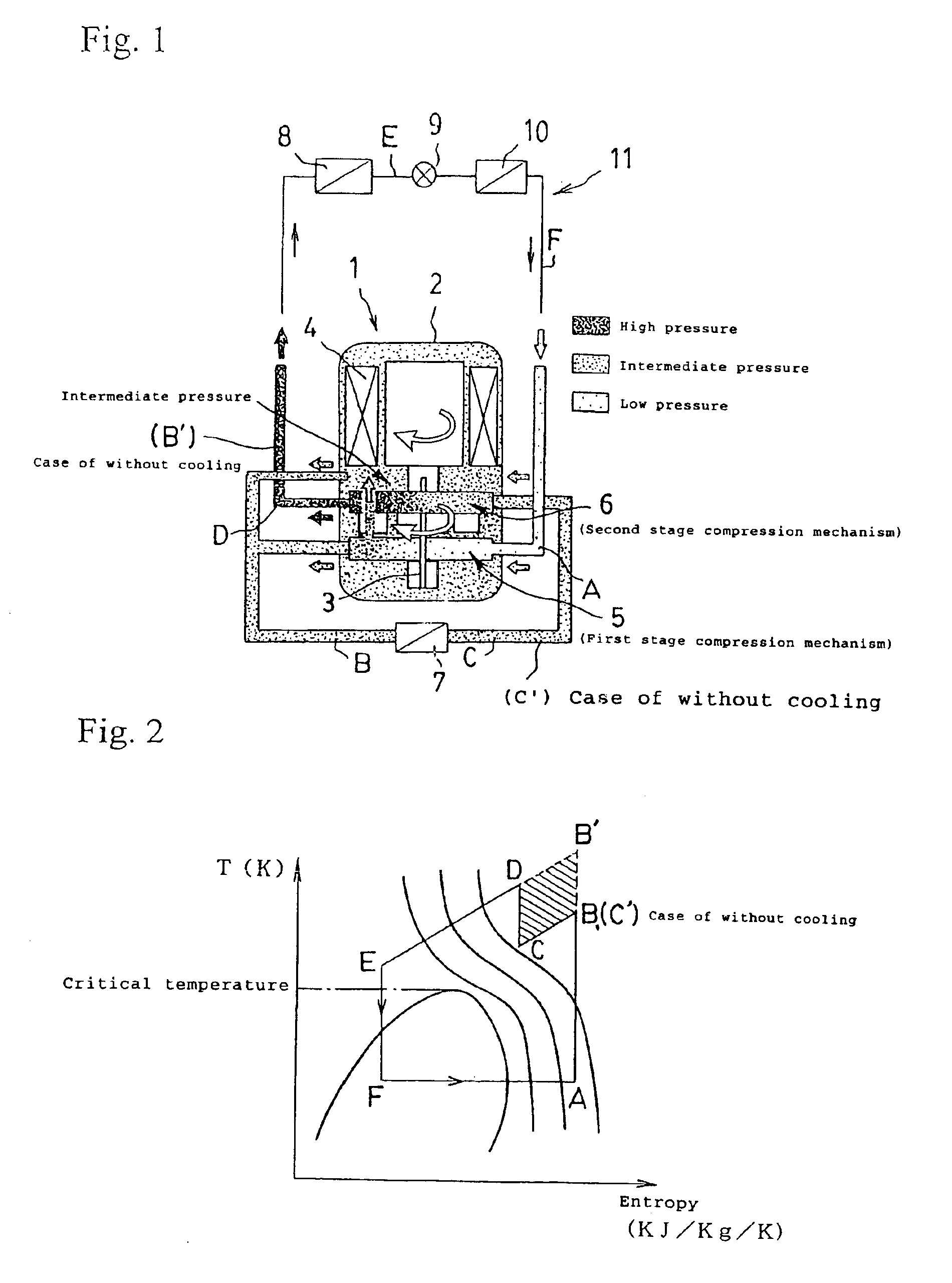
[0025]In FIG. 1, a two-stage compression system compressor 1 to be used for the present invention comprises a motor 4 having a drive shaft 3 above in a closed vessel 2 and a first stage compression mechanism (rotary system) 5 to be driven by the drive shaft 3 at the lowest part in the closed vessel 2 and a second stage compression mechanism (rotary system) 6 in a way to interlock with a phase difference of 180 degrees, a low pressure refrigerant (3 megapascals) is sucked by the first stage compression mechanism (rotary system) 5 passing through F→A as shown by the arrow, the refrigerant gas compressed to an intermediate pressure (megapascals) splits partially into the closed vessel 2, while the other splits to an external piping, refrigerant split into 2 paths joins again outside the closed vessel 2, thereafter, passes through B and is cooled down in the refrigerant heat exchanger 7, and the coole...


PUM


Abstract

The present invention concerns an on-vehicle air-conditioner, resolving problems of the prior art, and allowing to perform cooling, heating, dehumidification or others efficiently even for vehicles of low waste heat, such as hybrid cars taking electricity and gasoline as energy source, idle stop coping cars or battery cars taking only electricity as energy source, or other vehicles, by cooling by loading a refrigeration circuit, using for example CO2 refrigerant, and provided with an electrically driven two-stage compression system compressor, and at the same time, installing a refrigerant heat exchanger for cooling the refrigerant, compressed in the first stage in a way to exchange heat with the car interior air, and using conveniently also for heating together with the heat of the cooling water for cooling the engine.

Description

FIELD OF THE INVENTION[0001]The present invention concerns an on-vehicle air-conditioner used for vehicles of low waste heat such as hybrid cars using electricity and gasoline as energy source, idle stop coping cars, or others.BACKGROUND ART[0002]Ordinary vehicles travel taking the power out of an internal combustion engine using gasoline as fuel, and such vehicles have an on-board refrigeration circuit, and the cooling is performed by evaporating refrigerant in an evaporator for performing the cooling, and cooling the car interior air by the generated cold heat.[0003]In addition, the heating is performed by heating the car interior air by the heat of the cooling water for cooling the engine.[0004]Nonetheless, as such vehicles take out the driving force through combustion of gasoline or others, the control or regulation of hazardous materials contained in the exhaust gas thereof comes to be desired zealously.[0005]Moreover, conventionally, as refrigerant for cooling and refrigeratio...

Claims


Application Information

Patent Timeline
IPC IPC(8): B60H1/32B60H1/00F04C29/04F04C23/00F25B1/10F25B9/00F25B31/00F25B13/00B60H1/22F04C18/356F25B1/00
CPCB60H1/00007B60H1/3204B60H1/3205F04C23/001F04C23/008F04C29/04F25B1/10F25B9/008F25B31/006B60H1/00907F25B2400/072B60H2001/00935F04C18/3564F04C2210/1027F04C2210/222F04C2210/26F04C2210/261F25B13/00F25B2309/061
Inventor EBARA, TOSHIYUKIMUKAIYAMA, HIROSHIKUWABARA, OSAMUISHIHARA, TOSHIKAZU
Owner SANYO ELECTRIC CO LTD
Learn More