
Method for controlling rotary speed of cooling fan of vehicle and hybrid car

A cooling fan and speed control technology, which is applied in the field of vehicles, can solve the problems of long time, large heat dissipation of the cooling system, and unfavorable temperature of the cooling components for the normal operation of the vehicle.

Inactive Publication Date: 2013-01-09
SAIC MOTOR
View PDF6 Cites 24 Cited by
  • Summary
  • Abstract
  • Description
  • Claims
  • Application Information

AI Technical Summary

Problems solved by technology

In the prior art, the cooling fan of the vehicle is always at the same speed state, and at the initial stage of vehicle operation, the heat dissipation of each heat dissipation system is small, and after the vehicle has been running for a long time, the heat dissipation of each heat dissipation system is relatively large, resulting in the temperature of the vehicle's outlet air being high during operation. Too low, the temperature is too high after long-term operation, and the temperature of the cooling parts is too low or too high, which is not conducive to the normal operation of the vehicle
[0004] Especially for hybrid vehicles, in the pure electric drive mode, the coolant in the engine circulation system is cooled too much. When the user wants to change from the pure electric drive mode to the engine drive mode, it takes a long time and consumes a lot of power

Method used


Image

  • Method for controlling rotary speed of cooling fan of vehicle and hybrid car
  • Method for controlling rotary speed of cooling fan of vehicle and hybrid car
  • Method for controlling rotary speed of cooling fan of vehicle and hybrid car

Examples


Embodiment Construction

[0028] In order to make those skilled in the art better understand the technical solutions of the present invention, the present invention will be further described in detail below with reference to the accompanying drawings and specific embodiments.

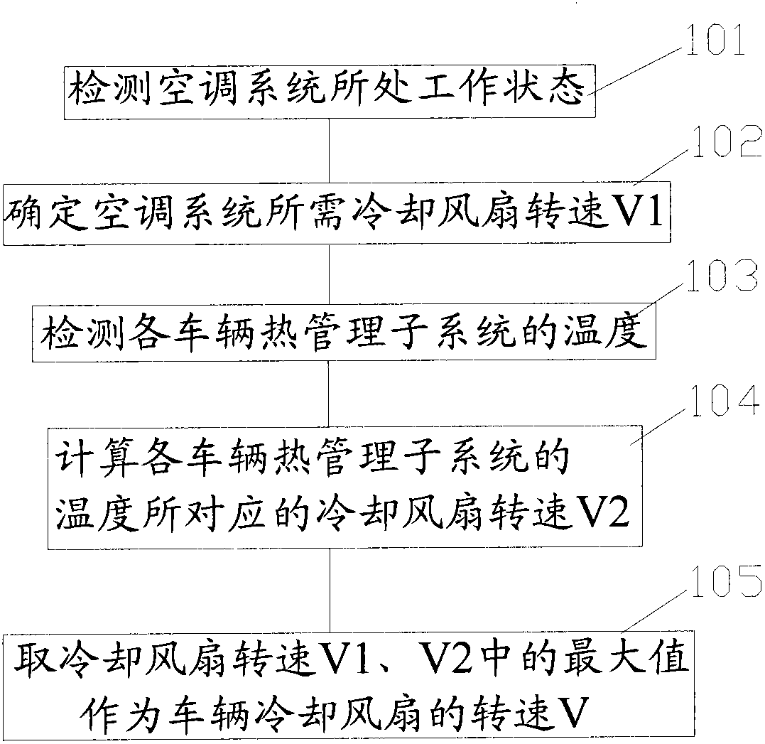
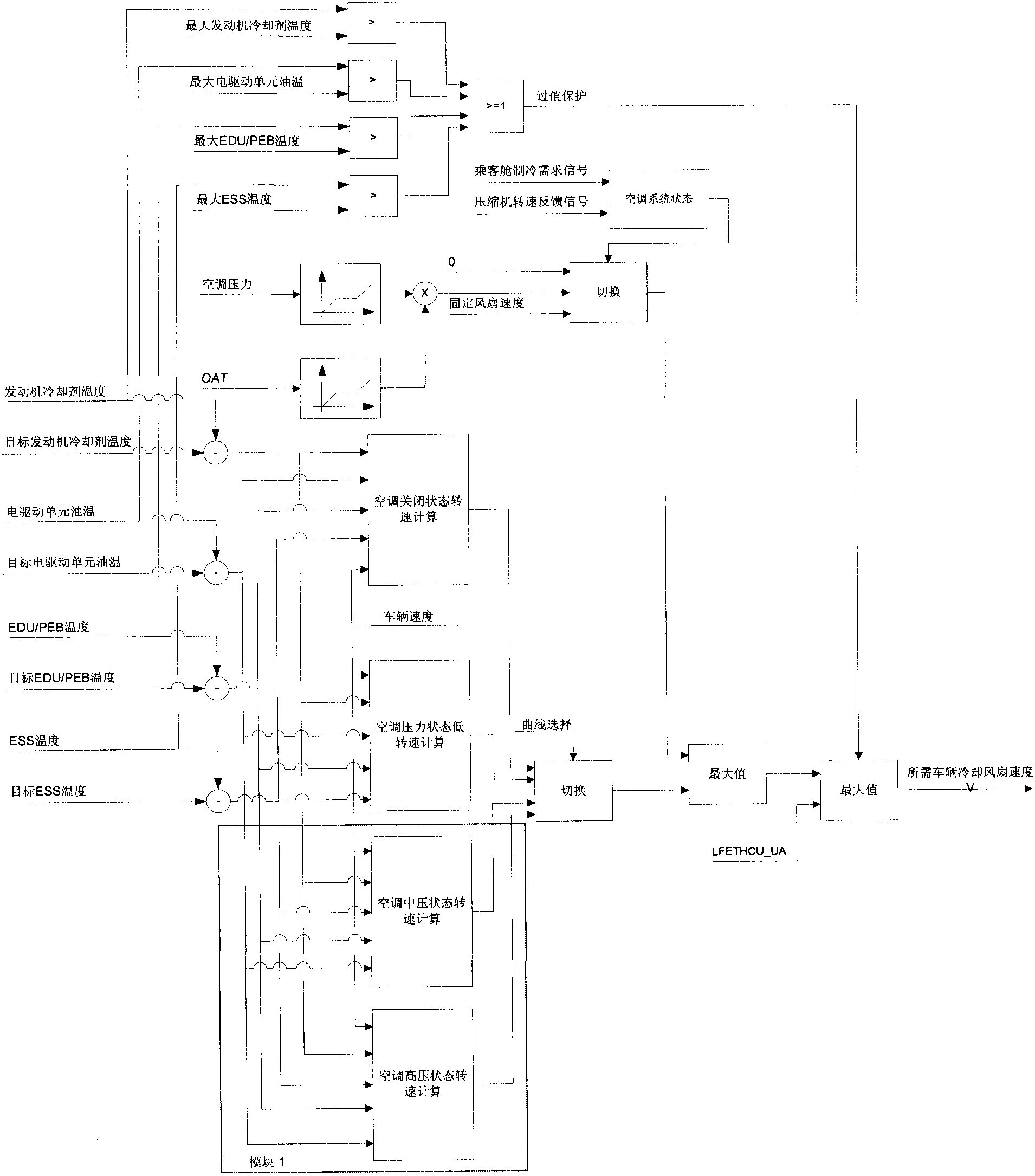
[0029] Please refer to figure 1 , figure 2 , figure 1 is a flow chart of a specific implementation of the method for controlling the rotational speed of a vehicle cooling fan provided by the present invention, figure 2 It is a logic block diagram of a specific implementation manner of the method for controlling the rotational speed of a vehicle cooling fan provided by the present invention.

[0030] like figure 1 , figure 2 As shown, the method for controlling the rotational speed of the vehicle cooling fan provided by the present invention can protect the following steps.

[0031] Step 101, detecting the working state of the air conditioning system. In the specific scheme, the working state of the air conditioning syst...


PUM


Abstract

The invention relates to the technical field of vehicles and discloses a method for controlling rotary speed of a cooling fan of a vehicle. The method comprises the following steps: detecting the working state of an air conditioning system in real time; determining the rotary speed V1 of the cooling fan needed by the air conditioning system; detecting the temperature of a heat management subsystem of each vehicle; calculating the rotary speed V2 of the cooling fan corresponding to the temperature of the heat management subsystem of each vehicle when the air conditioning system is under the working state; and comparing the rotary speeds V1 and V2 of the cooling fan, and adopting the maximum value of the two values as the rotary speed V, and controlling the cooling fan of the vehicle to work at the rotary speed V. With the adoption of the method for controlling rotary speed of the cooling fan of the vehicle, the heat for each heat dispassion system of the vehicle can be fully emitted, the temperature of some heat dispassion system can be prevented from being too low, the rotary speed of the cooling fan of the vehicle can be can adjusted according to the needs of the heat dispassion system of the vehicle, and the condition that each heat dispassion system is under the best working state is ensured. The invention further provides a hybrid car.

Description

technical field [0001] The present invention relates to the technical field of vehicles, and in particular, to a method for controlling the rotational speed of a cooling fan of a vehicle. The present invention also relates to a hybrid vehicle cooled by the above-mentioned vehicle cooling fan rotational speed control method. Background technique [0002] Vehicles, especially hybrid vehicles, will generate a lot of heat during operation. For example, the air conditioning system will generate a certain amount of heat during operation, and the engine cooling system, electric drive unit, power electronic mold case / electronic drive unit, battery, etc. The management subsystem generates a lot of heat during the working process. In order to ensure the normal operation of the above systems, a vehicle cooling fan is usually used to cool and dissipate the above systems. [0003] The cooling temperature produced by the vehicle cooling fan depends on the rotational speed of the vehicle ...

Claims


Application Information

Patent Timeline
IPC IPC(8): B60K11/06
Inventor 张良薛剑波王泰华袁励王天英
Owner SAIC MOTOR
Learn More