
Electrical energy system in a hybrid car

a hybrid car and electric energy technology, applied in hybrid vehicles, electric propulsion mounting, battery/fuel cell control arrangement, etc., can solve the problems of affecting the overall efficiency of the power train, and less energy available from these phases for electrical motor propulsion, etc., to achieve optimal absorbable recovered energy

Active Publication Date: 2005-12-22
VOLKSWAGEN AG
View PDF8 Cites 25 Cited by
  • Summary
  • Abstract
  • Description
  • Claims
  • Application Information

AI Technical Summary

Benefits of technology

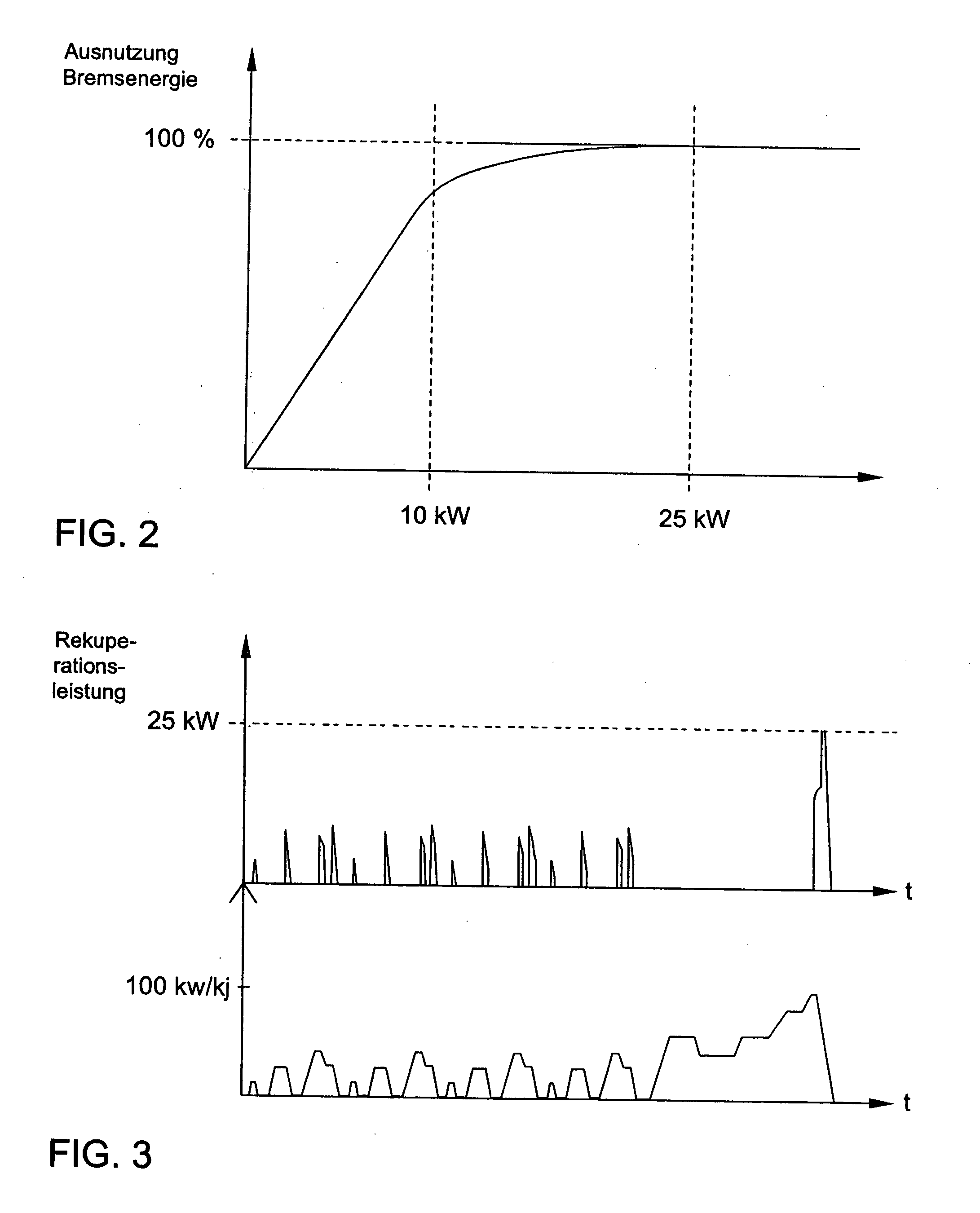
[0026] Another solution is to select a ratio between capacitor store energy content and electrical motor output ranging from 5 to 25 kJ/kW, preferably ranging from 5 to 20 kJ/kW, and even more preferred is a range from 5 to 15 kJ/kW. In the process the energy content of the capacitor store should always relate to the useful voltage lift, i.e. the limitation of the lower voltage level by the temporarily parallel switchable b

Problems solved by technology

The operation via the electrical motor may be limited for example to the range where little power is required and where a combustion engine is not very efficient, while higher power requirements are used to reload the electrical energy stores (which drive the electrical motor) via the combustion engine that is relatively efficient at that stage, plus via the dynamic operation of the electrical motor.
On the other hand, if the electrical motor and the combustion engine cannot be decoupled mechanically it is from an energy standpoint not advantageous to use only an electrical drive because the drag of the motor still has to be overcome, which would noticeably impair the overall efficiency of the power train.
However, since the energy recovered in the braking phases turns out to be in this case less because of the additional braking effect of the motor drag, less energy is available from these phases for propulsion by the electrical motor.
However, when it comes to optimizing the overall system for the most efficient fuel consumption possible, these are initially relegated to the background.
They have the advantage of relatively high volume and mass-related energy density, but they are limited in terms of the energy input and output that can be achieved.
Furthermore, the life of the battery is limited by the energy throughput (i.e. absorbed and emitted energy), with the result that heavy cycling reduces the life of the battery.
The disadvantage of a capacitor store versus a battery is above all the noticeably lower storable energy relative to volume (energy density).
This means that a capacitor store may be able to provide only a relatively small energy amount in case of stress because of the limited space available in the vehicle.

Method used


Image

  • Electrical energy system in a hybrid car
  • Electrical energy system in a hybrid car
  • Electrical energy system in a hybrid car

Examples


Embodiment Construction

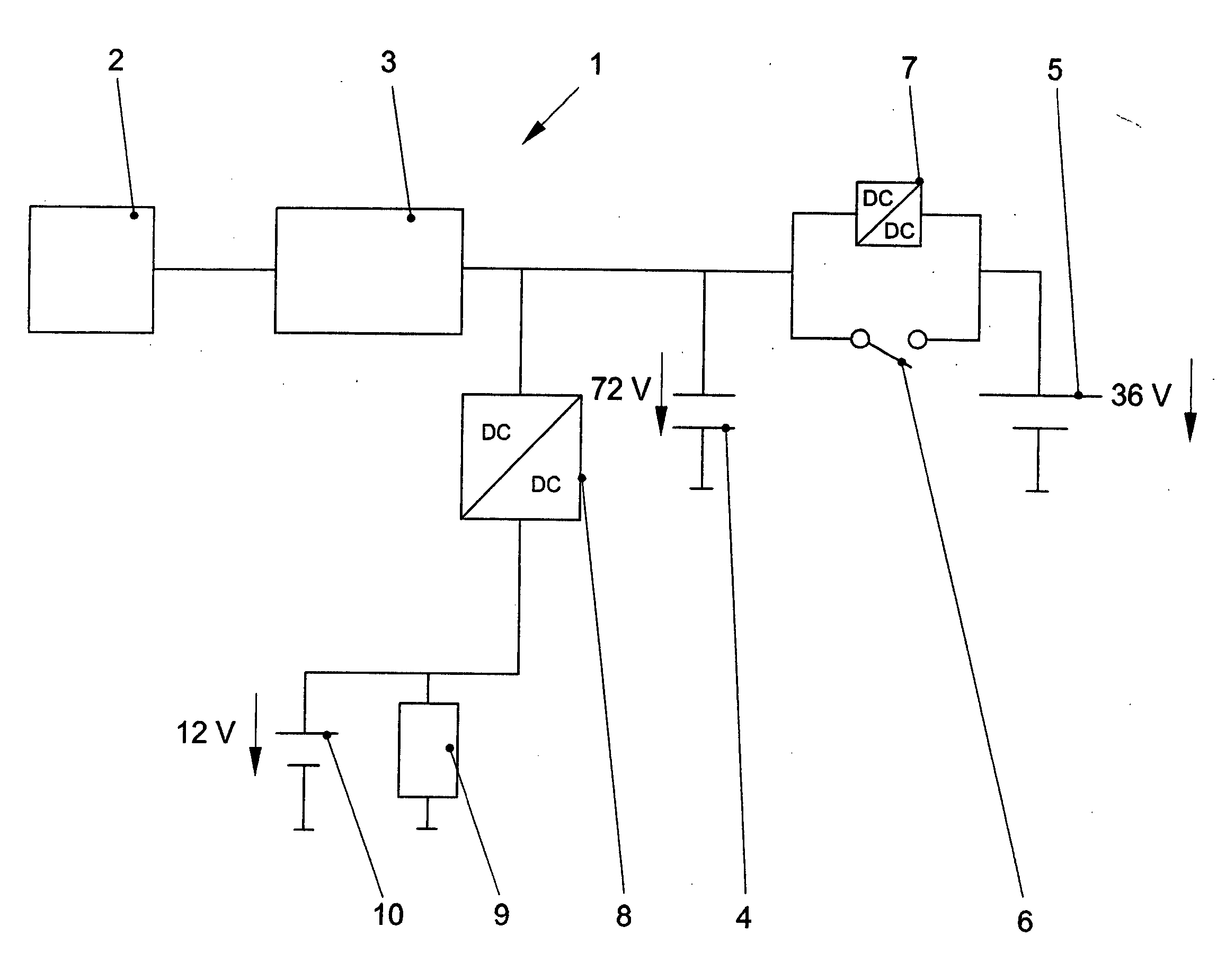
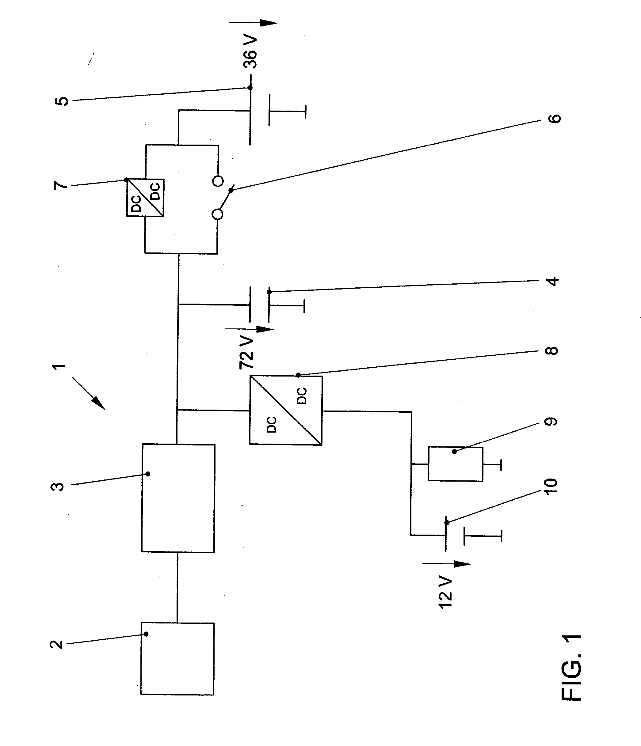
[0032]FIG. 1 shows the electrical energy system 1 in a hybrid car with an internal combustion engine 2. The electrical energy system 1 includes an electrical motor 3, a capacitor 4, a battery 5, a switch 6, a first DC / DC converter 7, a second DC / DC converter 8, a power supply user 9 and a power supply battery 10.

[0033] The internal combustion engine 2 is designed, by way of an example, as a direct-injection, lean-mixture diesel engine and is connected to the electrical motor 3 firmly or via a detachable clutch. The electrical motor 3 is designed for example as a crankshaft starter generator and can be operated mechanically and also dynamically. Mechanically the electrical motor 3 can start the internal combustion engine 2 and can mechanically support it (boost operation). Dynamically the electrical motor 3 can be driven by a gear, not shown, via the internal combustion engine 2 or via recovery. The rated voltage of the capacitor 4, designed preferably as a double-layer capacitor, i...


PUM


Abstract

An electrical energy system (1) in a hybrid car comprises an electrical motor (3), a capacitor (4) and a battery (5). The capacitor (4) is connected electrically to the electrical motor (3) and the capacitor (4) is switched in parallel with the battery (5) and the capacitor (4) has a rated voltage greater than 60V and the battery (5) has a rated voltage of less than 60V.

Description

CROSS-REFERENCE TO RELATED APPLICATION [0001] This application claims priority from German Patent Application No. 10 2004 023 619.4, which was filed on May 10, 2004, and is incorporated herein by reference in its entirety. TECHNICAL FIELD [0002] The invention concerns an electrical energy system in a hybrid car. BACKGROUND [0003] Hybrid cars combine two power trains that provide power in different ways for the propulsion of the vehicle. The properties of a combustion engine and an electrical motor are a particularly good fit, which is the reason why most of the hybrid cars today have such a combination. Today, parallel hybrid concepts in which the vehicle is propelled both by the combustion engine and the electrical motor are given preference over the serial hybrid concepts in which propulsion is provided basically by the electrical motor while the combustion engine generates the electrical current for loading the energy stores or directly for driving the electrical motor. [0004] Wi...

Claims


Application Information

Patent Timeline
IPC IPC(8): B60K1/00B60K6/28B60K6/485B60L50/15
CPCB60K6/28B60K6/485B60L11/1868B60W10/26H02J1/08Y02T10/7066H02J2001/008Y02T10/6226Y02T10/6278Y02T10/7005H02J7/345B60L58/20H02J1/082Y02T10/62Y02T10/70Y10S903/903Y10S903/907
Inventor POTT, EKKEHARDHOLZ, MATTHIASZILLMER, MICHAELHLADUN, MARC
Owner VOLKSWAGEN AG
Learn More