Input device

a technology of input device and touch control, which is applied in the direction of instruments, computing, electric digital data processing, etc., can solve the problems of user's difficulty in operating the key combination, the above method may not do the user too much good, and the reciprocal movement may be troublesome for users, so as to save user's trouble during operation.

Inactive Publication Date: 2009-09-10
DARFON ELECTRONICS CORP
View PDF6 Cites 24 Cited by
  • Summary
  • Abstract
  • Description
  • Claims
  • Application Information

AI Technical Summary

Benefits of technology

[0007]The invention is directed to an input device, a first action or a second action are performed according to the content of a touching signal being received, so that a keyboard can perform two different actions, saving user's trouble during operation.

Problems solved by technology

During long duration of use, the user may find the reciprocal movements troublesome.
However, the above method does not do the user too much good.
The user has to remember many key combinations, and this method is difficult to those who are not skilled in operating the key combinations.

Method used


Image

  • Input device
  • Input device
  • Input device

Examples


first embodiment

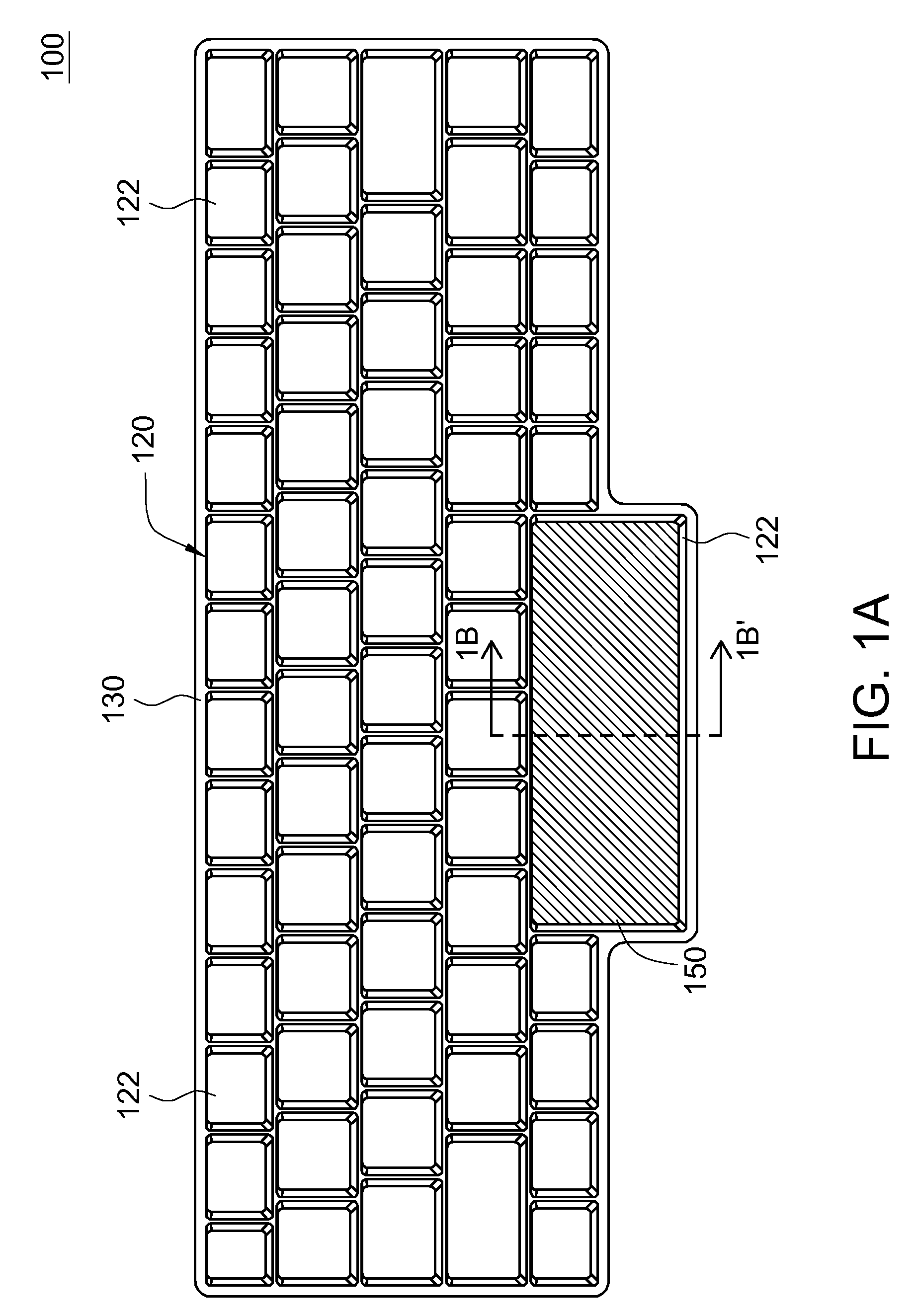
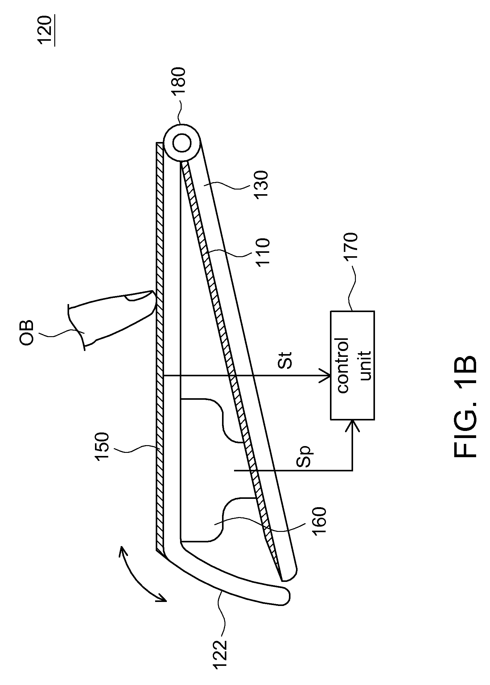
[0025]Referring to FIG. 1A and FIG. 1B at the same time. FIG. 1A shows a top view of an input device according to a first embodiment of the invention. FIG. 1B shows a cross-sectional view along a cross-sectional line 1B-1B′ of FIG. 1A. The input device 100 includes a base 130, a keyboard structure 120, a touch panel 150, a press-sensing element 160 and a control unit 170. The keyboard structures 120 are disposed above the base 130. The touch panel 150 is disposed above the base 130. When the touch panel 150 is touched by an object OB, the touch panel 150 generates a touching signal St. The press-sensing element 160 is disposed between the base 130 and the touch panel 150. When the press-sensing element 160 senses that the touch panel 150 is touched by the object OB, the press-sensing element 160 generates a pressing signal Sp. At the time that the control unit 170 receives the pressing signal Sp, the control unit 170 performs a first action or a second action according to the conten...

second embodiment

[0032]Referring to FIG. 6, a cross-sectional view of an input device according to a second embodiment of the invention is shown. The keyboard structure 220 of the second embodiment moves the keys 240 upward and downward by way of a bar linkage 280. The second embodiment differs with the first embodiment in the mechanism of moving the key 240 upward and downward when the key 240 is pressed, and other similarities are not repeated here.

[0033]In the present embodiment of the invention, the keyboard structure 220 preferably includes a plurality of keys 240 and a bar linkage 280. Only a key 240 and a bar linkage 280 are illustrated in FIG. 6. The bar linkage 280 is disposed between the base 130 and key 240. The bar linkage 280 includes two rods coupled to each other, wherein one end of each rod is coupled to the base 130, and the other end of each rod is disposed on the bottom surface of the key 240. Thus, each key 240 can move relatively to the base 130 upward and downward by way of the...

third embodiment

[0034]Referring to at the same time FIG. 7A and FIG. 7B. FIG. 7A shows a top view of an input device according to a third embodiment of the invention. FIG. 7B shows a cross-sectional view along a cross-sectional line 7B-7B′ of FIG. 7A. The touch panel 350 of the third embodiment is disposed among a plurality of keys 322 of the keyboard structure 320. The third embodiment differs with the first embodiment in the design of disposing the touch panel 350, and other similarities are not repeated here.

[0035]The input device 300 includes a base 330, a keyboard structure 320, a touch panel 350, a press-sensing element 160 and a control unit 170. The keyboard structures 320 are disposed above the base 330. The touch panel 350, moving relatively to the base 330 upward and downward, is disposed above the base 330. When the touch panel 350 is touched by an object OB, the touch panel 350 generates a touching signal St. The press-sensing element 160 is disposed between the base 330 and the touch ...


PUM


Abstract

An input device is provided. The input device includes a base, a keyboard structure, a touch panel, a press-sensing element and a control unit. The keyboard structure is disposed above the base. The touch panel moving relative to the base upward and downward is disposed above the base. When the touch panel is touched by an object, the touch panel generates a touching signal. The press-sensing element is disposed between the base and the touch panel. When the press-sensing element senses that the touch panel is pressed by the object, the press-sensing element generates a pressing signal. At the time that the control unit receives the pressing signal, the control unit performs a first action or a second action according to the content of the touching signal being received.

Description

[0001]This application claims the benefit of Taiwan application Serial No. 97107955, filed Mar. 6, 2008, the subject matter of which is incorporated herein by reference.BACKGROUND OF THE INVENTION[0002]1. Field of the Invention[0003]The invention relates in general to an input device, and more particularly to an input device with touch control function.[0004]2. Description of the Related Art[0005]Nowadays, most electronic devices have an input interface for the user to operate with. Examples of the interface include keyboard, mouse, key set and touch panel. The user operates the built-in software of the electronic device to capture data, input data1 communicate with other electronic device or get connected to the Internet by the interface.[0006]Currently, the most popular input method is implemented by a keyboard accompanied by a mouse or a keyboard accompanied by a touch panel. As the keyboard and the mouse are two different entities, when the user types via the keyboard, if the us...

Claims


Application Information

Patent Timeline
Patent Type & Authority Applications(United States)
IPC IPC(8): G06F3/041
CPCG06F3/021G06F3/04883G06F3/0414G06F3/03547
Inventor LIU, CHIA-HUNG
Owner DARFON ELECTRONICS CORP
Why Eureka
Try Eureka