Spatial motion calculation apparatus and method for the same

a technology of spatial motion and calculation apparatus, which is applied in the field of spatial motion calculation apparatus, can solve the problems of large noise in the estimation of spatial positions, disadvantageously difficult to estimate and difficult to calculate spatial motion in a stable manner by using methods of related, so as to achieve the effect of maximizing the integration similarity

Active Publication Date: 2009-09-10
KK TOSHIBA
View PDF3 Cites 21 Cited by
  • Summary
  • Abstract
  • Description
  • Claims
  • Application Information

AI Technical Summary

Benefits of technology

[0008]According to an embodiment of the invention, the present embodiment provides a spatial motion calculation apparatus including a first input unit configured to input image positions, spatial positions, and feature descriptors of a plurality of first feature points within a tracked area of an object of interest before the object moves;a second input unit configured to input image positions, spatial positions, and feature descriptors of a plurality of second feature points within an area of containing the object of interest after the object has moved; an image position relation calculation unit configured to determine each of first similarity functions based on the image position of each of the plurality of first feature points and the image position of each of the plurality of second feature points, each of the first similarity functions (1) containing the shift on the image and a parameter representing the depth direction on the image as unknowns and (2) having a larger value when the distance between the image position of each of the plurality of first feature points and the image position of each of the plurality of second feature points is closer; a spatial position relation calculation unit configured to determine each of second similarity functions based on the spatial position of each of the plurality of first feature points and the spatial position of each of the plurality of second feature points, each of the second similarity functions (1) containing the shift on the image and the parameter representing the depth direction on the image as unknowns and (2) having a larger value when the distance between the spatial position of each of the plurality of first feature points and the spatial position of each of the plurality of second feature points is closer;a feature descriptor relation calculation unit configured to determine each of third similarity functions based on the feature descriptor of each of the plurality of first feature points and the feature descriptor of each of the plurality of second feature points, each of the third similarity functions having a larger value when the feature descriptor of each of the plurality of first feature points and the feature descriptor of each of the plurality of second feature points are more similar; an integration unit configured to determine the shift on the image and the parameter representing the depth direction on the image that maximize an integrated similarity determined by the sum of the products of the first similarity functions, the second similarity functions, and the third similarity functions; and

Problems solved by technology

However, spatial positions are estimated, for example, based on the principle of triangulation using a plurality of TV cameras or other similar devices, so that the estimated spatial positions may contain large amounts of noise.
In this case, it is difficult to calculate the spatial motion in a stable manner by using methods of related art.
Further, when spatial positions contain noise, it is disadvantageously difficult to estimate the spatial motion in a stable manner.

Method used


Image

  • Spatial motion calculation apparatus and method for the same
  • Spatial motion calculation apparatus and method for the same
  • Spatial motion calculation apparatus and method for the same

Examples


first embodiment

[0020]A spatial motion calculation apparatus according to a first embodiment of the invention will be described with reference to FIGS. 1 to 5A and 5B.

[0021]The spatial motion calculation apparatus calculates the spatial motion of the center of gravity of an object (a human being, a vehicle, and other objects) 101 moving through space between the positions of the object before and after the movement.

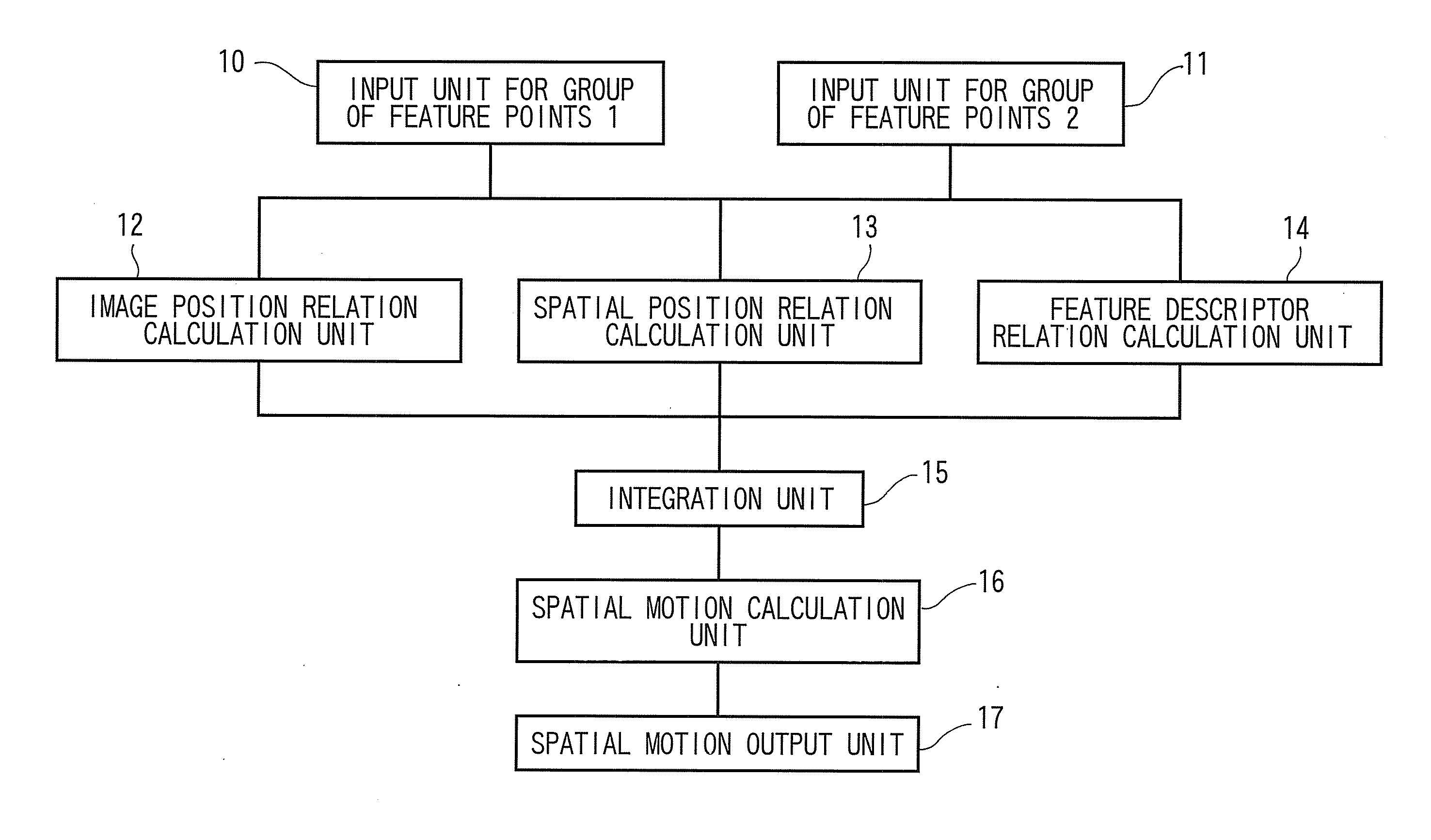
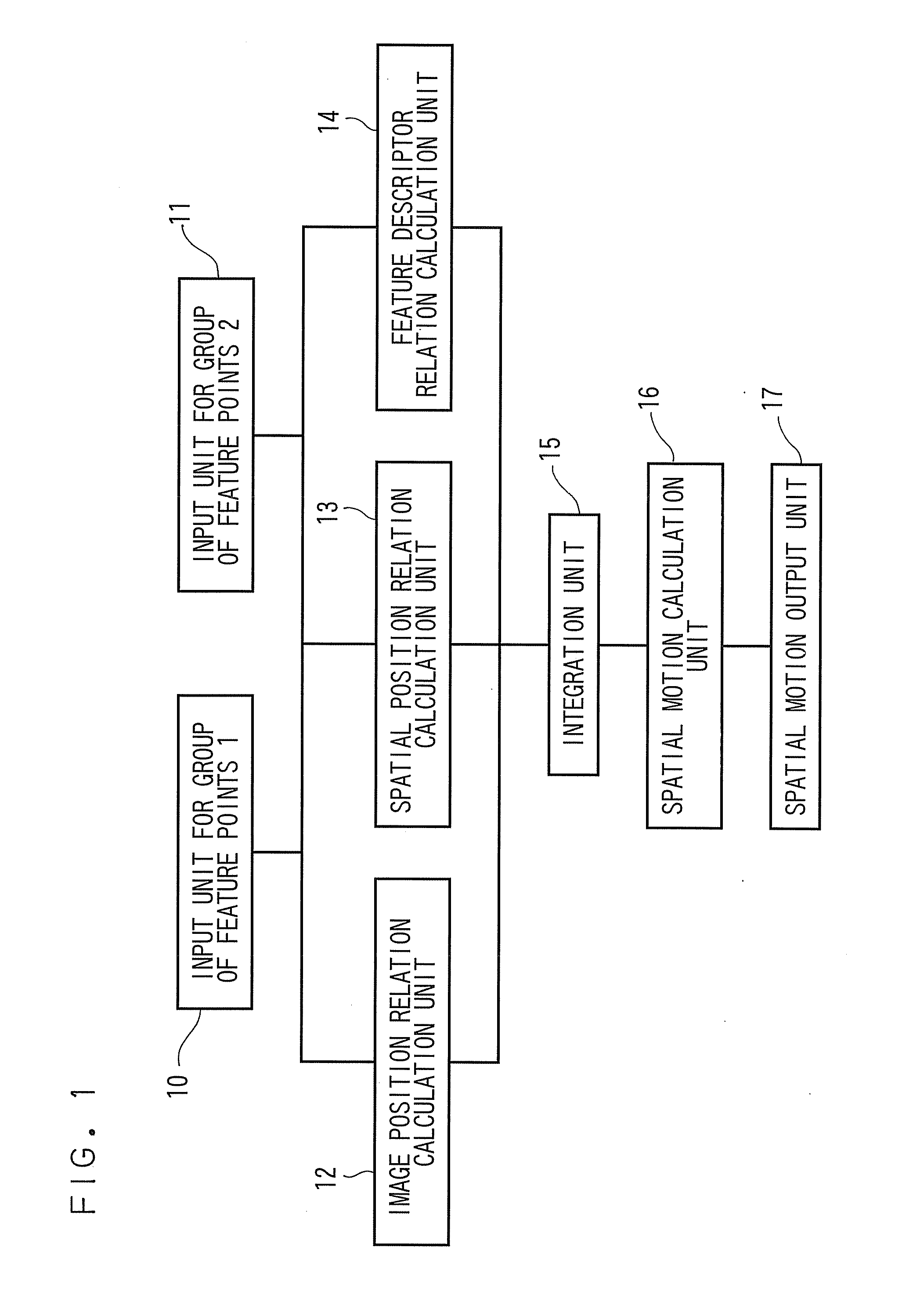
[0022]FIG. 1 is a block diagram showing the spatial motion calculation apparatus.

[0023]The spatial motion calculation apparatus includes an input unit 10 that inputs image positions, spatial positions, and feature descriptor of a plurality of feature points (hereinafter referred to as “a group of feature points 1”) in a tracked area before the object 101 moves, an input unit 11 that inputs image positions, spatial positions, and feature descriptor of a plurality of feature points (hereinafter referred to as “a group of feature points 2”) in an area containing the tracked subject after th...

second embodiment

[0079]A spatial motion calculation apparatus of a second embodiment will be described with reference to FIGS. 6 and 7.

[0080]The configuration of the spatial motion calculation apparatus according to the present embodiment is the same as that in the first embodiment (see FIG. 1). The present embodiment, however, differs from the first embodiment in that a position X in the spatial coordinate system is not used but a disparity d is used to calculate the spatial motion.

[0081]The disparity d is the difference in the u-axis direction between a position projected onto a 1st reference image 103 and a position projected onto a 2nd reference image 104, as shown in FIG. 7. For example, the disparity for X* is u*-u″*. Let O-XYZ coordinate system be a 1st reference coordinate system at the center of which a 1st reference camera is located; O″-X″Y″Z″ be a 2nd reference coordinate system at the center of which a 2nd reference camera is located; and b be the base length between O and O″. When the ...

third embodiment

[0117]A spatial motion calculation apparatus of a third embodiment will be described with reference to FIGS. 8 and 9.

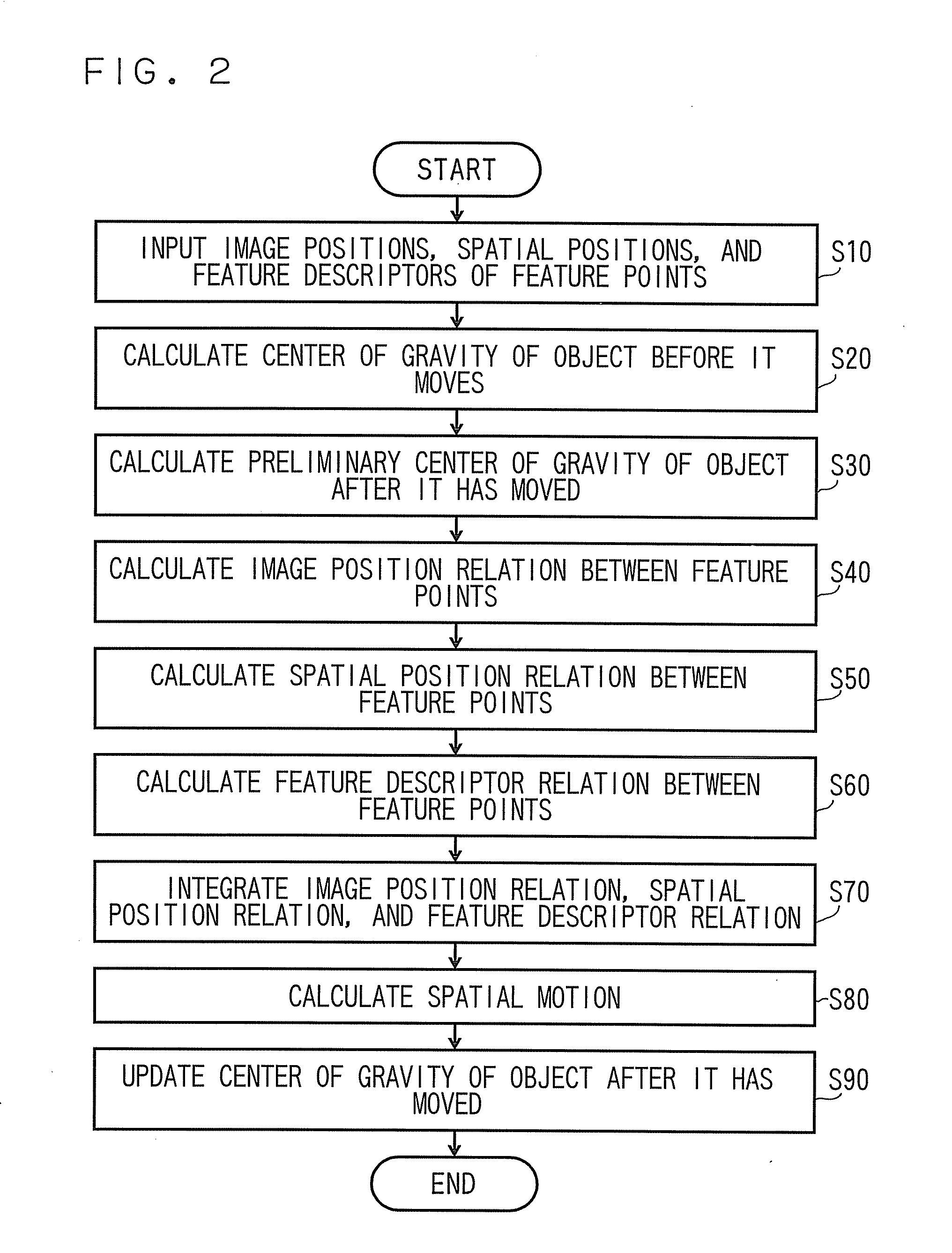
[0118]FIG. 8 is a block diagram showing the configuration of the spatial motion calculation apparatus according to the present embodiment, and FIG. 9 is a flowchart for the same.

[0119]FIG. 8 is a block diagram showing the configuration of the spatial motion calculation apparatus according to the present embodiment.

[0120]The spatial motion calculation apparatus includes an input unit 10 that inputs image positions, spatial positions, and feature descriptors of a group of feature points 1, an input unit 11 that inputs image positions, spatial positions, and feature descriptors of a group of feature points 2, an image position relation calculation unit 12 that calculates a first similarity based on the image position relation between the inputted groups of feature points 1 and 2, a spatial position relation calculation unit 13 that calculates a second similarity based on...


PUM


Abstract

A spatial motion calculation apparatus includes an image position relation calculation unit that calculates first similarities based on an image position relation between an inputted groups of feature points 1 and 2, a spatial position relation calculation unit that calculates second similarities based on an spatial position relation between said inputted groups, a feature descriptor relation calculation unit that calculates third similarities based on a feature descriptor relation between said inputted groups, and a spatial motion calculation unit that estimates the spatial motion based on the result that integrates the first to third similarities.

Description

CROSS-REFERENCE TO RELATED APPLICATION[0001]This application is based upon and claims the benefit of priority from the prior Japanese Patent Application No. 2008-59840, filed on Mar. 10, 2008; the entire contents of which are incorporated herein by reference.FIELD OF INVENTION[0002]The present invention relates to a spatial motion calculation apparatus and a method for the same in which a TV camera or any other similar device images an object moving through space to estimate the three-dimensional movement of the object.DESCRIPTION OF THE BACKGROUND[0003]When stereo cameras or any other similar device is used to track an object moving through space, the tracking has not been carried out by considering the total relationship among image positions, spatial positions, and feature descriptor (e.g., brightness ) of feature points on the moving object (see, for example, JP-A-10-27249(Kokai), and Tyagi et al., “Fusion of Multiple Camera Views for Kernel-Based 3D Tracking,” IEEE Workshop on ...

Claims


Application Information

Patent Timeline
Patent Type & Authority Applications(United States)
IPC IPC(8): G06K9/00
CPCG06T7/2033G06T2207/30196G06T2207/10021G06T7/2086G06T7/246G06T7/285
Inventor SEKI, AKIHITO
Owner KK TOSHIBA
Why Eureka
Try Eureka