Dual stage clutch

a clutch and dual stage technology, applied in the direction of gearing control, belt/chain/gearing, gearing element, etc., can solve the problems of loss of power, limited mass of flyweights, and still suffer significant disadvantages, so as to reduce the risk of belt slippage, and reduce the effect of belt slippag

Active Publication Date: 2009-09-10
BEYER MARK
View PDF5 Cites 27 Cited by
  • Summary
  • Abstract
  • Description
  • Claims
  • Application Information

AI Technical Summary

Benefits of technology

[0013]One advantage of the present invention centers on two sets of flyweights or cam arms, each set consisting of a plurality of flyweights that are mounted on a separate rotatable member of the clutch such that each set of flyweights has a different axis of rotation. The flyweights each have an engageable cam surface that relates engine revolutions-per-minute to the input / output revolution ratio to effect a simulated gear shifting transmission characteristic.
[0014]Another advantage of the present invention is directed to flyweights made of different materials and weights to obtain a desired centrifugal action, and the mounting of flyweights having predetermined centers of mass to obtain the greatest mechanical advantage at the optimum time during the shifting process and variable ratio of the transmission. One of the sets of the flyweights is mounted in a manner to create a supplemental dual force to help eliminate belt slippage during high load use.
[0015]It is still another advantage of the present invention to provide an improved centrifugal clutch that imparts increased force at inertial shift.
[0016]It is yet another advantage of the present invention to provide an improved centrifugal clutch that affords increased performance for high performance engines, including lower RPM higher horsepower engines, due to the application of more force than by prior clutch mechanism.
[0017]Embodiments of the present invention use flyweights on two distinct rotatable members of the clutch that lie in two different parallel planes. The utilization of flyweights on two separate members creates massive adjustable force in the first ¼ to ¾ of the shift then signs off or stops engagement letting the flyweights on only one of the members to complete the shifting of the sheaves. This is a significant improvement over prior clutches that use only flyweights on one rotating member.
[0018]These and other features and advantages of this invention will become more apparent to those skilled in the art from the detailed description of a preferred embodiment. The drawings that accompany the detailed description are described below.

Problems solved by technology

An undesirable result of these CVT systems is a tendency to lose power because of belt slippage due to insufficient belt side force while the vehicle is accelerating to near maximum speed.
while the clutch disclosed in Berto yields some benefits, it still suffers from significant disadvantages.
For example, due to the side-by-side arrangement of the first and second set of flyweights, the mass of the flyweights is limited due to space constraints and structural integrity constraints.
Because of the limited mass of the flyweights, this arrangement cannot provide sufficient force necessary to perform the function of today's high performance engines.

Method used


Image

  • Dual stage clutch
  • Dual stage clutch
  • Dual stage clutch

Examples


Embodiment Construction

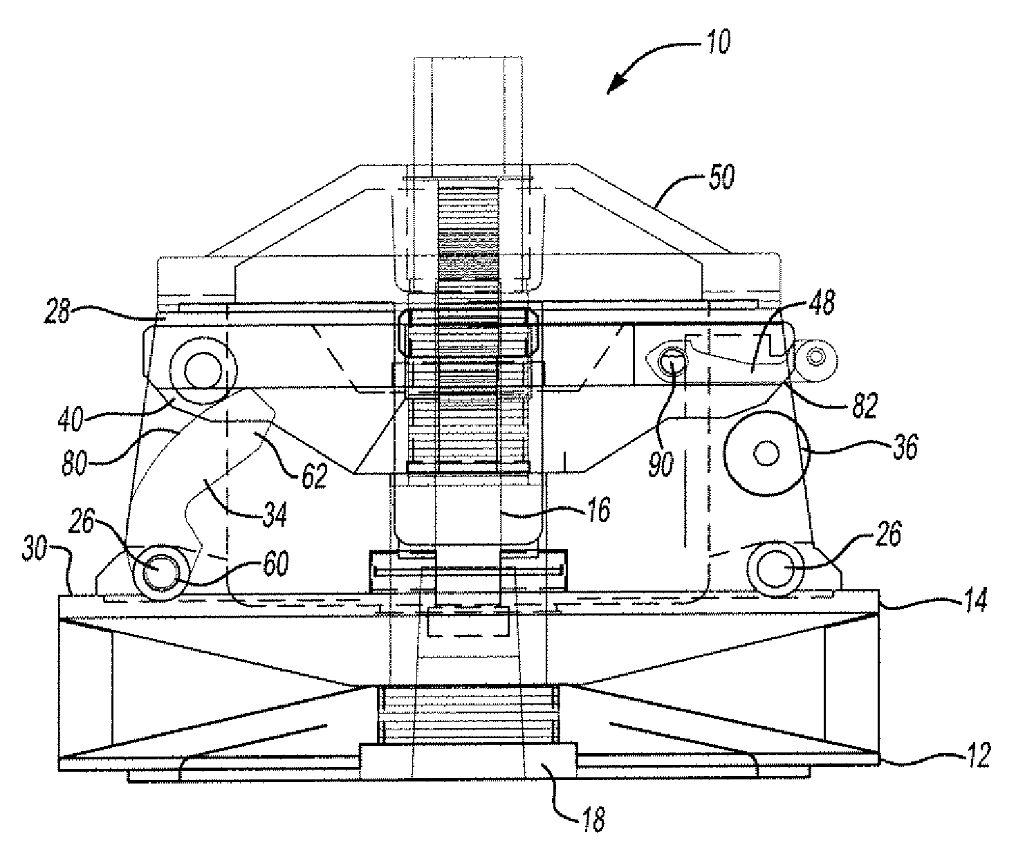
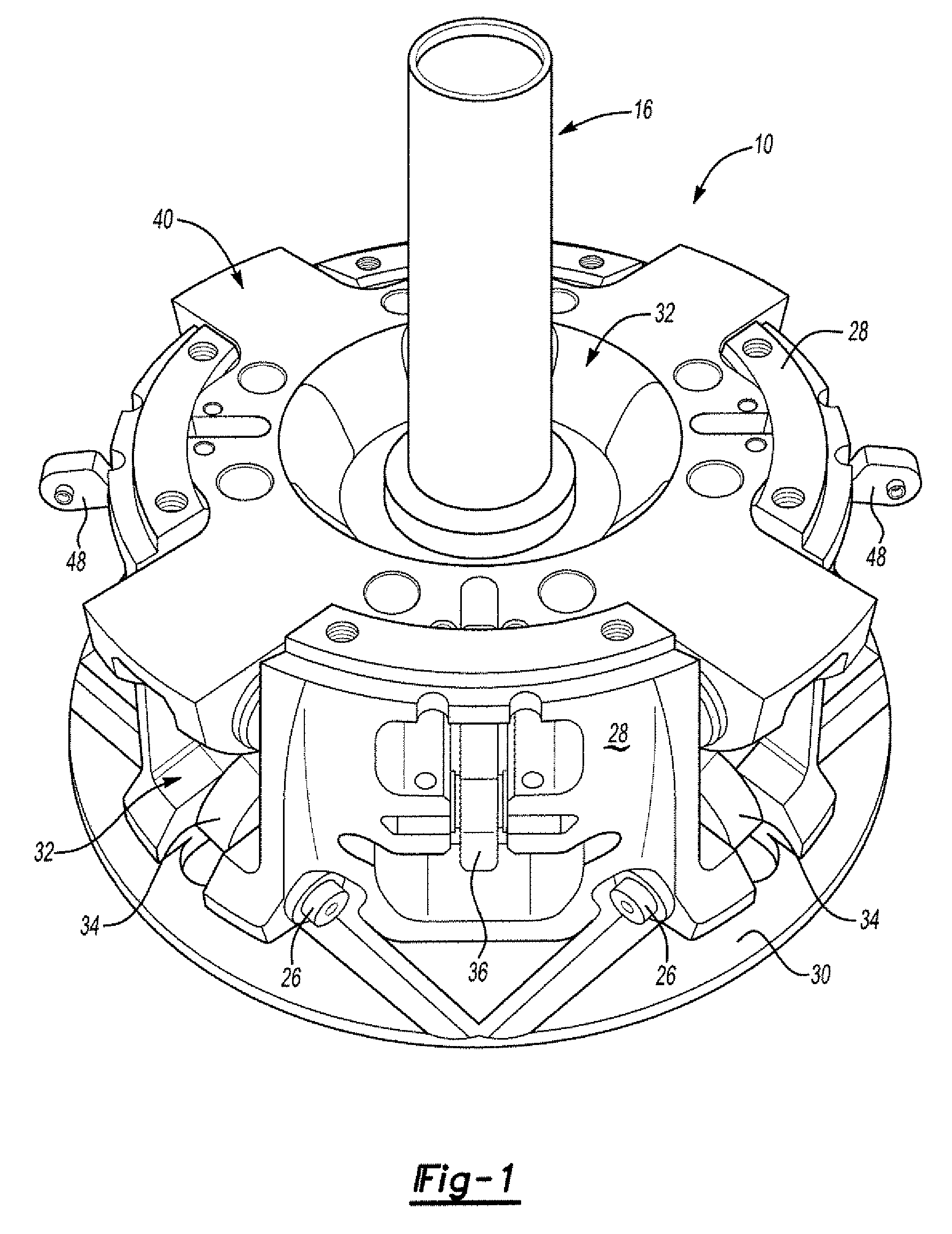
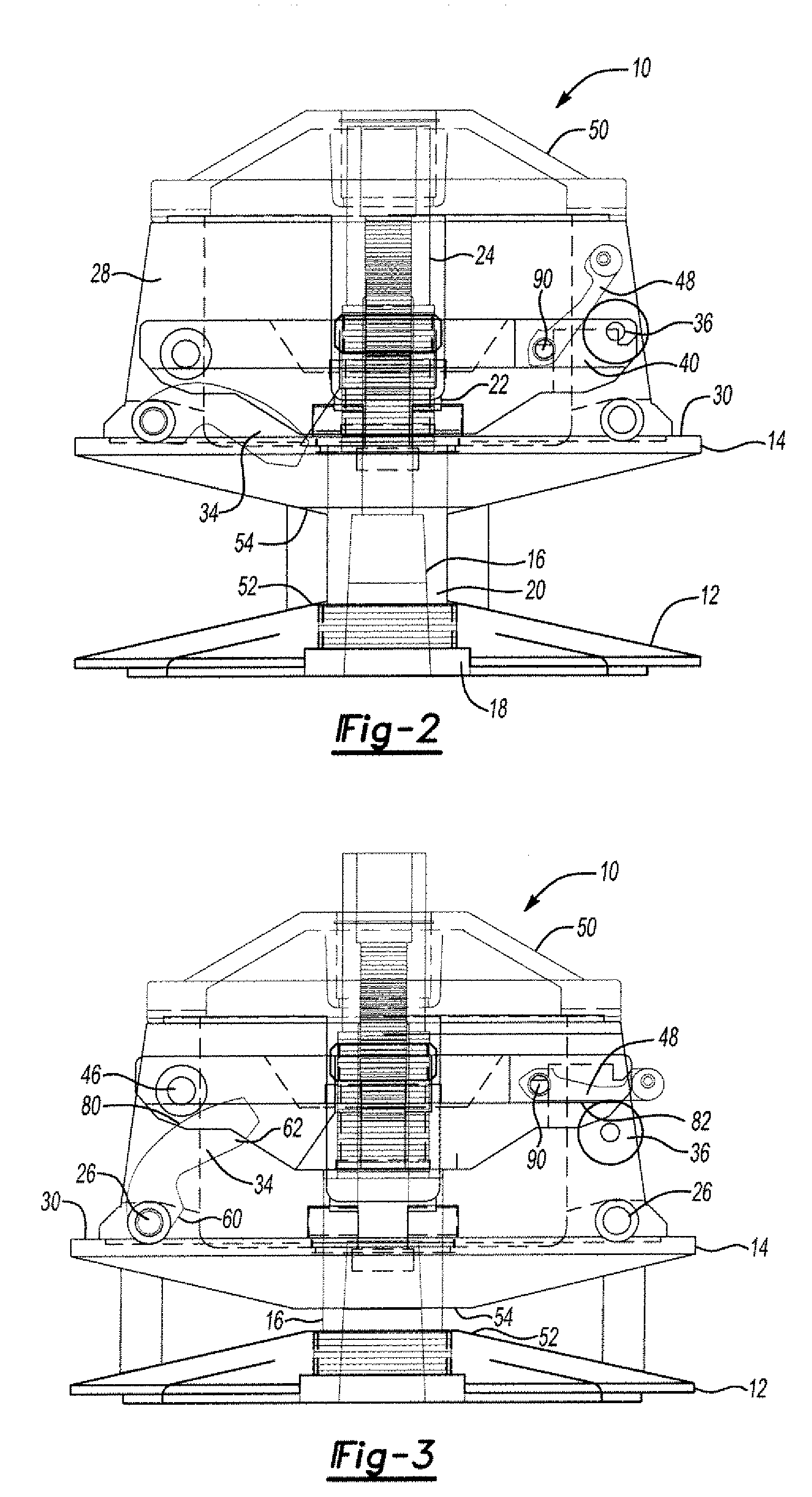
[0025]The disclosure is directed to an improved centrifugal clutch the structure of which permits its use with engines having different performance characteristics, and enables simple adjustable modification resulting in a desired performance relationship with the selected engine and different operating environments. One feature centers on the inclusion of a plurality of flyweights, each having an engageable cam surface that relates engine revolutions-per-minute to the input / output revolution ratio to effect a simulated gear shifting transmission characteristic. Other features are directed to flyweights made of different materials and weights to obtain the proper centrifugal action, and the mounting of flyweights having predetermined centers of mass to obtain the greatest mechanical advantage at the optimum time during the shifting process and variable ratio of the transmission, as is well known. Still another feature includes flyweights mounted in a manner to create a supplemental ...


PUM


Abstract

Continuously variable speed drive (CVT) have improved performance due to use of two groups of flyweight cams, each group being mounted on separate rotational members of a centrifugal clutch. One set of flyweight cams provides force to close the sheaves through the entire movement of the shift, whereas the other set of flyweight cams provides force only through an initial portion of the shift and then signs off. This provides a two stage shift behavior for the CVT that enhances power transfer to the driven pulley.

Description

CROSS-REFERENCE TO RELATED APPLICATIONS[0001]The present application claims priority from U.S. Provisional Patent Application Ser. No. 61 / 034,730, filed Mar. 7, 2008, and entitled “Dual Stage Clutch”, which is hereby incorporated by reference.TECHNICAL FIELD[0002]The present invention relates generally to clutch mechanisms. More particularly, the present invention relates to a clutch mechanism that provides a variable diameter for driving of an endless belt and which is adapted for use in connection with a high performance engine.BACKGROUND INFORMATION[0003]One class of conventional continuously variable transmissions (or “CVT's”) has two tapered-faced pulleys interconnected with a belt of essentially fixed length. The sheaves of each pulley are able, under control, to move axially. The pulley on one shaft is connected to the crankshaft of the engine. The system including the pulley, and its ancillary parts, that is connected to the engine is called the driving, driver, or primary c...

Claims


Application Information

Patent Timeline
Patent Type & Authority Applications(United States)
IPC IPC(8): F16H59/04
CPCF16H55/563F16H63/067F16H61/66245
Inventor BEYER, MARK
Owner BEYER MARK
Why Eureka
Try Eureka