Multi-compartmental prosthetic device with patellar component transition

a multi-compartmental, prosthetic technology, applied in the field of prosthetic devices, can solve the problems of inconvenient operation, and inability to achieve fit,

a multi-compartmental, prosthetic technology, applied in the field of prosthetic devices, can solve the problems of inconvenient operation, and inability to achieve fit,

US20090228111A1Active Publication Date: 2009-09-10MAKO SURGICAL CORP

Image

  • Multi-compartmental prosthetic device with patellar component transition
  • Multi-compartmental prosthetic device with patellar component transition
  • Multi-compartmental prosthetic device with patellar component transition

Examples


Embodiment Construction

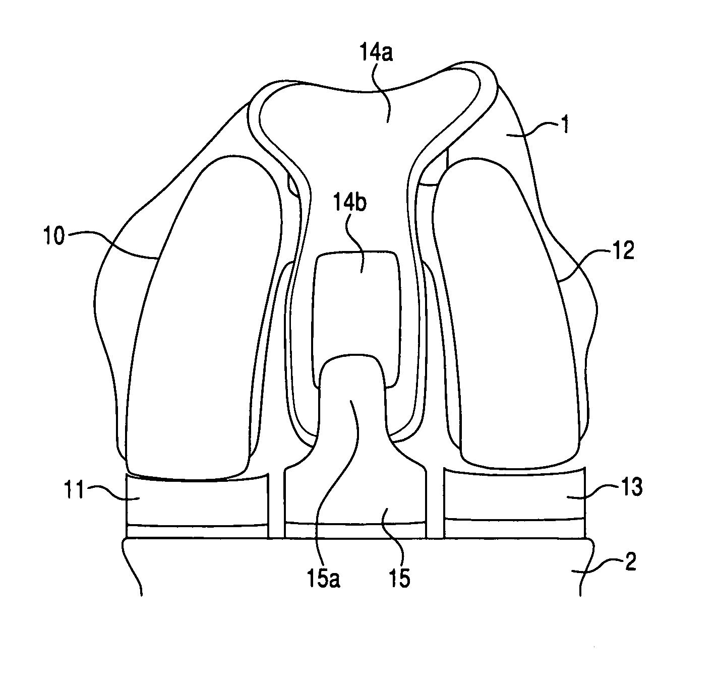
[0032]The following discloses embodiments of the present invention that provide techniques and implants that can be configured to enable individual components of a prosthetic device to be selected and implanted in one, two, or three compartments of a joint with a high degree of accuracy and in any combination that enables the surgeon to vary the geometry and configuration of the implant to create a customized prosthetic device tailored to the patient's unique anatomy, ligament stability, kinematics, and disease state. Moreover, the implant components can be configured to provide a smooth transition of the patella or patellar implant from component to component. Preferred embodiments are illustrated in the drawings. An effort has been made to use the same or like reference numbers throughout the drawings to refer to the same or like parts.

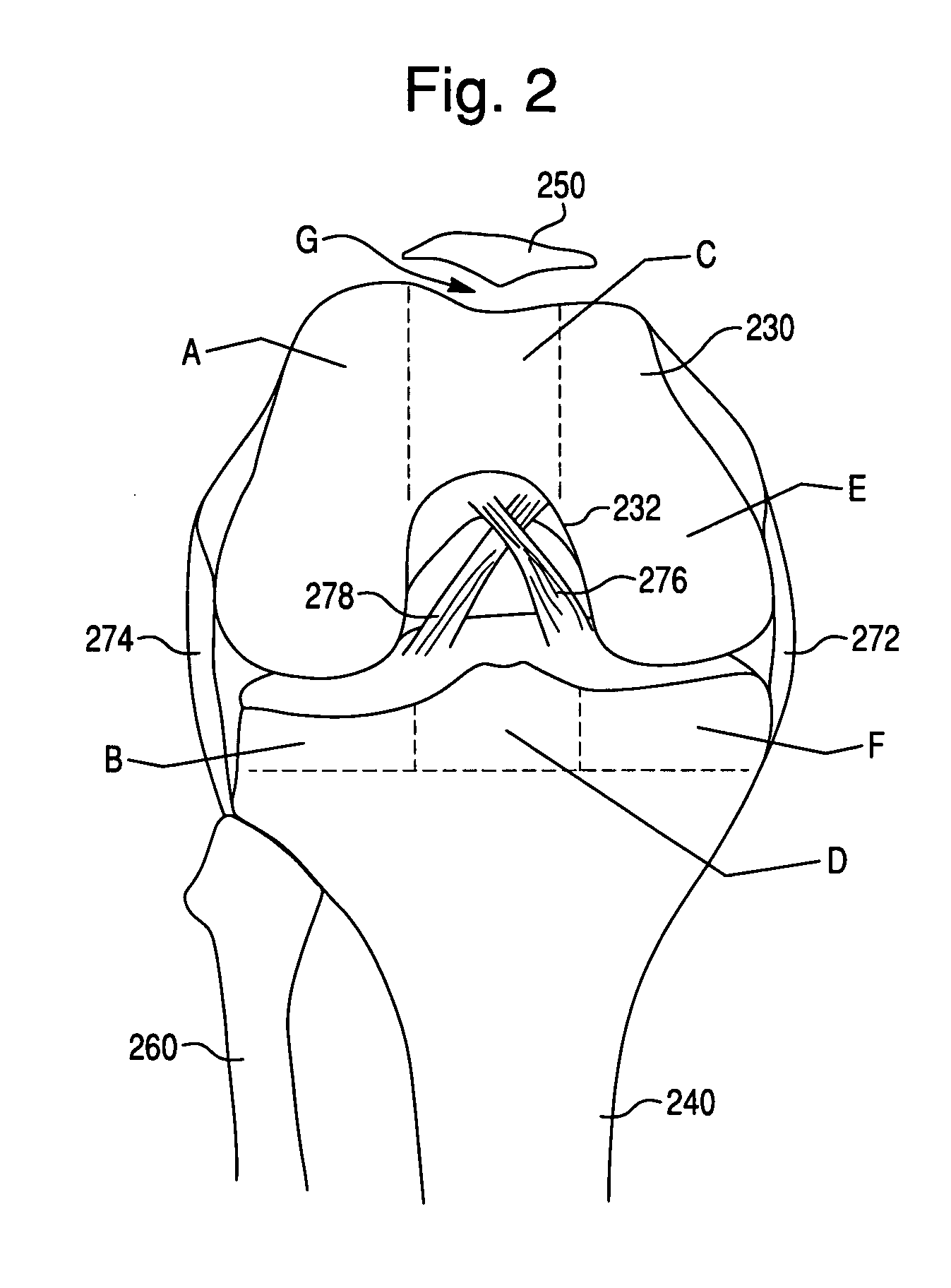
[0033]FIG. 2 is a diagram of a knee joint that includes a distal end of a femur 230, a proximal end of a tibia 240, a fibula 260, and a patella 250...


PUM


Abstract

A prosthetic device for forming at least a portion of a joint may have a plurality of segmented components fixed relative to a femur of a body including: a patellofemoral component and a condyle component. Each segmented component may be configured such that a placement at which the segmented component will be fixed relative to the femur is not constrained by a connection to another of the segmented components that is fixed relative to the femur. In an installed configuration, the patellofemoral and condyle components may be fixed relative to the femur such that: a gap is provided between an edge of the patellofemoral component and an opposing edge of the condyle component, and a transition region is provided that extends from a first femoral coronal plane that intersects the patellofemoral component to a second femoral coronal plane that intersects the condyle component.

Description

CROSS-REFERENCE TO RELATED PATENT APPLICATIONS[0001]The present application claims priority to U.S. Provisional Application Nos. 61 / 068,053, filed Mar. 4, 2008; 61 / 068,059, filed Mar. 4, 2008; and 61 / 194,941, filed Oct. 2, 2008, each of which is hereby incorporated herein by reference in its entirety.FIELD[0002]The present invention relates to a prosthetic device configured to form at least a portion of a joint and, more particularly, to such a prosthetic device with a transition region extending from a patellofemoral component to a condyle component.BACKGROUND[0003]As shown in FIG. 1, conventional total knee arthroplasty (TKA) systems typically include a femoral component 500 that is implanted on the distal end of the femur and replaces the bearing surfaces of the femur, a tibial component 502 that is implanted on the proximal end of the tibia and replaces the bearing surfaces of the tibia and meniscus, and a patellar component (not shown) that replaces the articular surface of the...

Claims


Application Information

Patent Timeline
10 Sep 2009
Publication
US20090228111A1
IPC
A61F2/38
CPC
A61F2/38; A61F2002/3895; A61F2/3877
Inventors
OTTO, JASON KARL