Accordingly, while dental implants should be designed to take into account this natural healing process of bone after
tooth loss, this is seldom the case.
This presents several problems.
Immediate placement
single stage implants do not lend themselves to
grafting procedures as the implant cannot be buried (two staged) and covered with a membrane to allow the gap between the implant and the extraction wall socket to fill with new bone.
Covering this open wound with a membrane such as the PRF (
platelet rich
fibrin) membrane is extremely important since getting primary
wound closure is difficult.
Furthermore, attempts mimicking the cemento-enamel junction (CEJ) of the
natural tooth do not take into account the healing morphology of the bony anatomy particularly when the implant was placed following the immediate placement protocol.
Implant designs have gone through a considerable amount of
trial and error in an attempt to deal with the issue of the bone not healing evenly once a tooth has been extracted.
Only a limited number of studies have been conducted regarding bone loss patterns following
tooth loss.
If an implant fixture is placed in the center of the maximum height of available bone, the implant can end up too far to the lingual from the point of view of the restorative dentist.
Accordingly, as the implant must be shorter in length than ideal, together with the increase in crown to root ratio, a weaker and less stable implant /
abutment complex results.
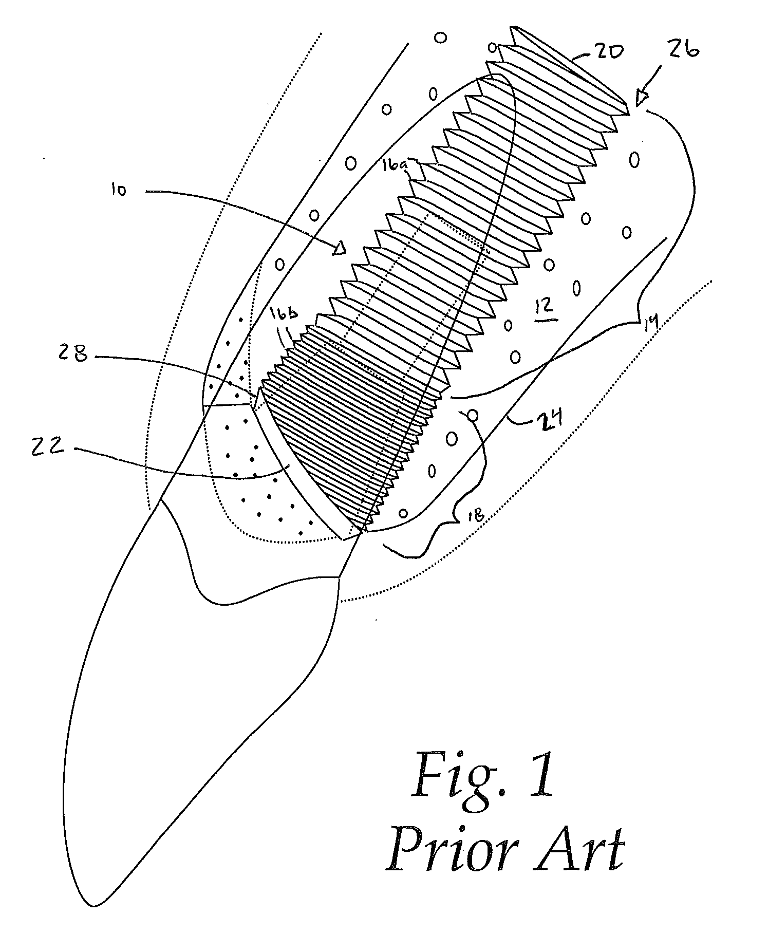
Another problem with burying implants is that loading forces typically produce a bone loss pattern referred to as cupping.
This cupping pattern usually stabilizes after about one year of function with vertical bone loss of approximately 2 mm but, by that time, loss of bone critical to the predictable support of overlying
soft tissue is lost.
While maximum height of available bone may be engaged, the exposed threads of the implant compromise the ideal
facial contour of the final restoration.
However, this kind of implant positioning may actually create the greatest problem for the restorative dentist as he must now attempt to position the abutment and final restoration in an off axial alignment with respect to the implant.
If the abutment and crown are misaligned to the implant, the tooth not only looks unattractive, but it may not be able to function properly due to unfavorable loading forces.
There are dental implants systems that typically do not demonstrate a cupping bone loss pattern or some of the other previously mentioned problems.
However, the Ankylos surgical protocol demands placing the implant two millimeters below the crest of bone in the
upper anterior region of the mouth which essentially creates a cupping or defect of the
crestal bone.
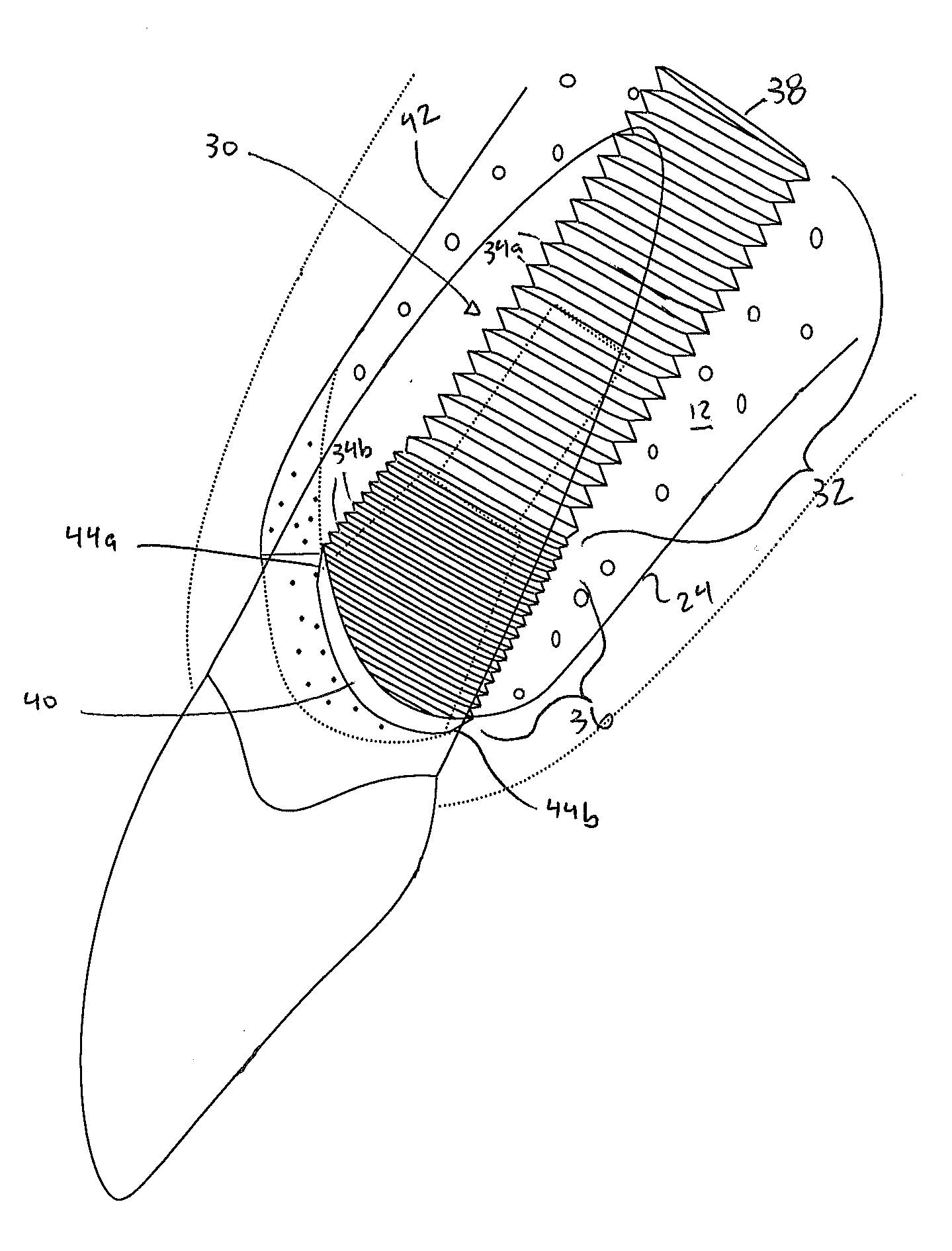
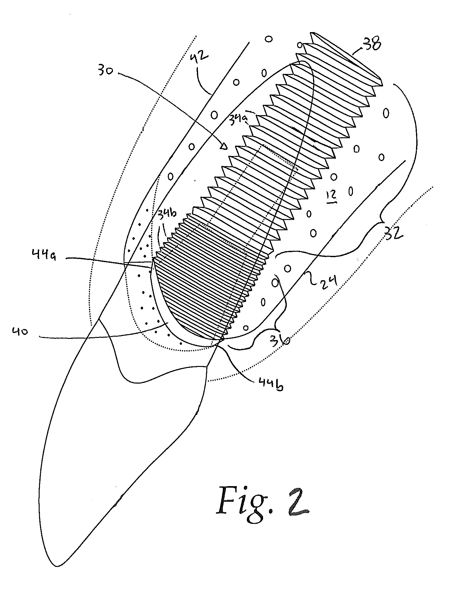
Implants duplicating tooth anatomy in some way, shape or form have not had the same level of clinical success as the sloped top design.
However, while the sloped top implant works very well with extraction sites that have been allowed to heal, and the implant placed following the delayed protocol, it may not be the most ideal design when implanted immediately following tooth extraction.
But fooling Mother Nature does have certain limitations.
Implants placed immediately do not fill the entire extraction socket as implants are generally somewhat undersized compared to the
natural tooth they are replacing since it has been shown that implants cannot be as close to neighboring natural teeth as the
natural tooth being replaced.

