
Touch event model

a multi-touch enabled device and event model technology, applied in multi-programming arrangements, instruments, computing, etc., can solve the problems of inability to split the display into different parts, difficulty in splitting the display, and inability to achieve so as to simplify the recognition of single and multiple touch events

Active Publication Date: 2009-09-10
APPLE INC
View PDF116 Cites 86 Cited by
  • Summary
  • Abstract
  • Description
  • Claims
  • Application Information

AI Technical Summary

Benefits of technology

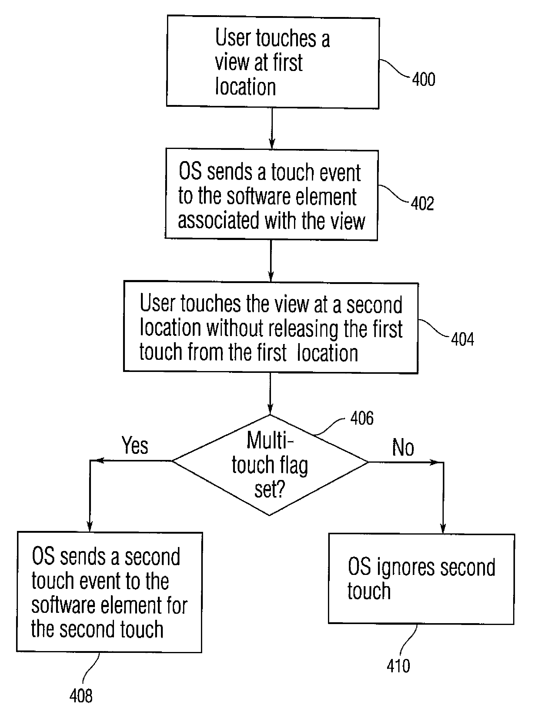
The present invention provides methods, software, devices, and APIs for defining touch events for application level software. It simplifies the recognition of single and multiple touch events for applications running in multi-touch enabled devices. By configuring each view within a window as either a multi-touch view or a single touch view, and as either an exclusive or a non-exclusive view, touch events in that view and other views can be either ignored or recognized. This allows for simpler applications or software elements that do not take advantage of advanced multi-touch features to be executed at the same device as more complex applications or software elements.

Problems solved by technology

While the benefits of multi-touch enabled interfaces are known, these devices can present some interface design challenges.
This can make it difficult to split the display into different portions and have different independent software elements process interactions associated with each portion.
However, if each application, process or other software element needs to consider multiple touch interactions, then the overall cost and complexity of software running at the multi-touch enabled device may be undesirably high.
More specifically, each application may need to process large amounts of incoming touch data.
This can require high complexity in applications of seemingly simple functionality, and can make programming for a multi-touch enabled device generally difficult and expensive.
Also, existing software that assumes a single pointing device can be very difficult to convert or port to a version that can operate on a multi-point or a multi-touch enabled device.

Method used


Image

  • Touch event model
  • Touch event model
  • Touch event model

Examples


Embodiment Construction

[0014]In the following description of preferred embodiments, reference is made to the accompanying drawings which form a part hereof, and in which it is shown by way of illustration specific embodiments in which the invention may be practiced. It is to be understood that other embodiments may be utilized and structural changes may be made without departing from the scope of the preferred embodiments of the present invention.

[0015]This relates to a touch event model that simplifies the recognition of single and multiple touch events for user interface applications running in multi-point and multi-touch enabled devices. To simplify the recognition of single and multiple touch events, each view within a particular window can be configured as either a multi-touch view or a single touch view. Furthermore, each view can be configured as either an exclusive or a non-exclusive view. Depending on the configuration of a view, touch events in that and other views can be either ignored or recog...


PUM


Abstract

Embodiments of the present invention are directed to methods, software, devices and APIs for defining touch events for application level software. Furthermore, some embodiments are directed to simplifying the recognition of single and multiple touch events for applications running in multi-touch enabled devices. To simplify the recognition of single and multiple touch events, each view within a particular window can be configured as either a multi-touch view or a single touch view. Furthermore, each view can be configured as either an exclusive or a non-exclusive view. Depending on the configuration of a view, touch events in that and other views can be either ignored or recognized. Ignored touches need not be sent to the application. Selectively ignoring touches can allow for simpler software elements that do not take advantage of advanced multi touch features to be executed at the same device and time as more complex software elements.

Description

FIELD OF THE INVENTION[0001]This relates to multi-point and multi-touch enabled devices in general, and more specifically to recognizing single and multiple point and touch events in multi-point and multi-touch enabled devices.BACKGROUND OF THE INVENTION[0002]Multi-touch enabled devices are known in the art. A multi-touch enabled device is a device that can sense multiple touches at the same time. Thus, a multi-touch enabled device can, for example, sense two touch events that take place simultaneously at two different positions on a multi-touch panel and are caused by two fingers being pressed down on the panel. Examples of multi-touch enabled devices are discussed in U.S. patent application Ser. No. 11 / 649,998, entitled “PROXIMITY AND MULTI-TOUCH SENSOR DETECTION AND DEMODULATION,” filed on Jan. 3, 2007 and hereby incorporated by reference in its entirety. Multi-point enabled devices define a more general set of devices that include multi-touch enabled devices as well as similar d...

Claims


Application Information

Patent Timeline
Patent Type & Authority Applications(United States)
IPC IPC(8): G06F9/46H04M1/72484
CPCG06F3/0488G06F3/017G06F3/041G06F3/04886G06F3/0482G06F3/04186G06F3/0416G06F3/0481G06F2203/04104G06F2203/04808G06F3/04883G06F2203/04803
Inventor BEAVER, JASON CLAYPLATZER, ANDREW
Owner APPLE INC
Learn More