
Latch mechanism

a technology of latch mechanism and latch rod, which is applied in the direction of latch applications, mechanical devices, fastening means, etc., can solve the problems of large amount of energy required to operate, large volume, and high cost of relatively powerful motors, and achieve the effect of improving the latch mechanism

Inactive Publication Date: 2009-09-17
MERITOR TECH
View PDF3 Cites 2 Cited by
  • Summary
  • Abstract
  • Description
  • Claims
  • Application Information

AI Technical Summary

Benefits of technology

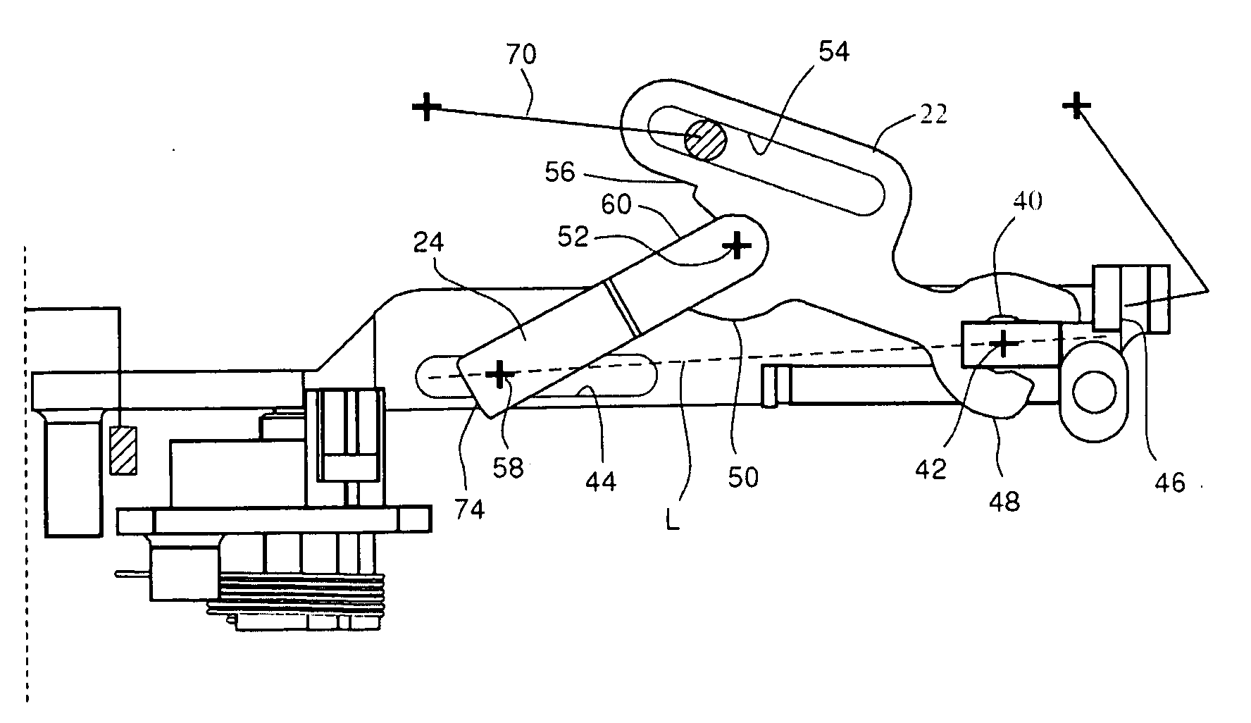
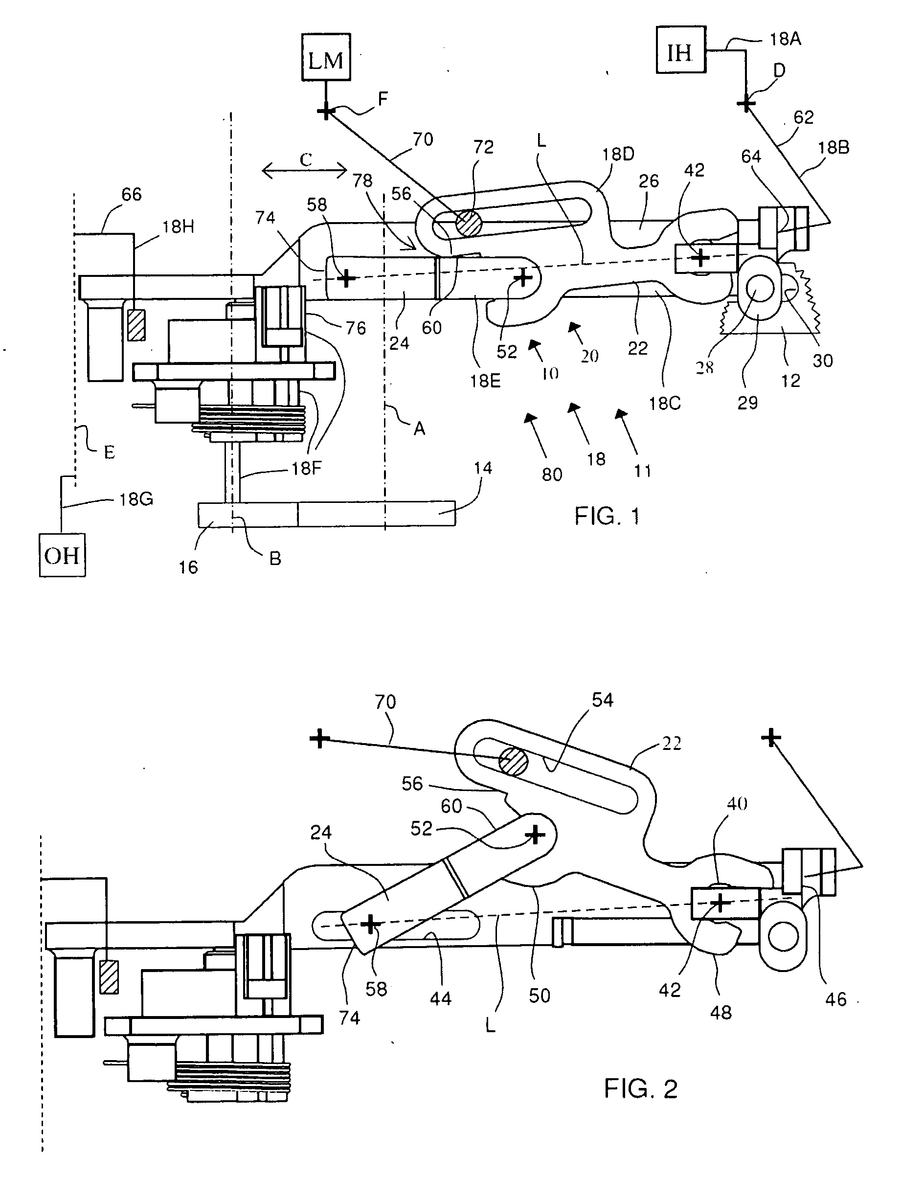
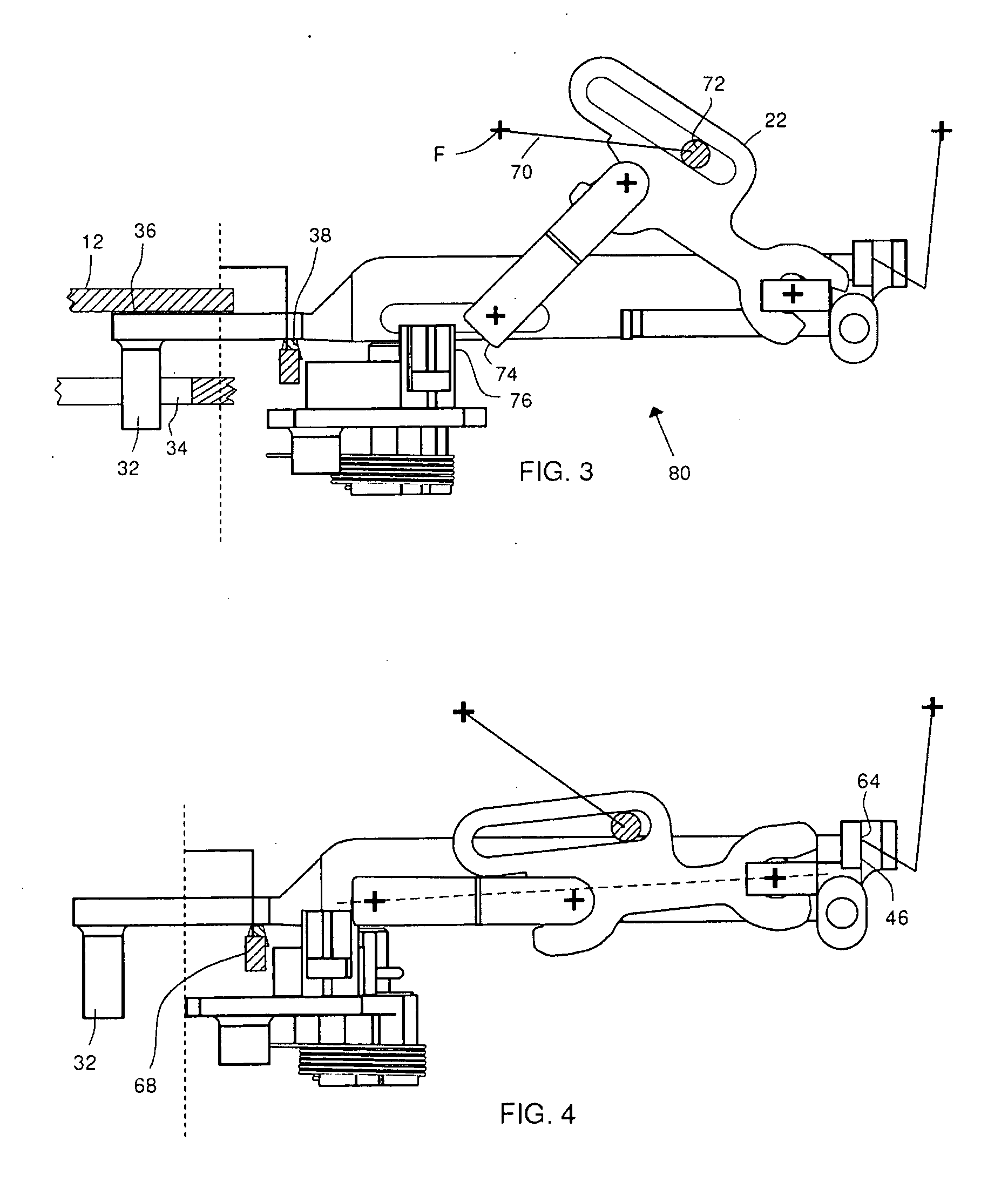
[0006]The present invention provides an improved latch mechanism. The latch mechanism includes a latch chassis, a latch bolt having a closed position and an open position, a pawl having an engaged position at which the pawl holds the latch bolt in the closed position and a disengaged position at which the pawl allows the latch bolt to move to the open position, and a first release handle operably connected to the pawl via a transmission path to selectively move the pawl from the engaged position to the disengaged position. The transmission path includes a toggle linkage having a first link pivotable about a first axis and a second link pivotable about a second axis. The first link and the second link are pivotable relative to each other about a common axis. The latch mechanism includes a stop to limit rotation of the second link in a first direction relative to the first link. The toggle linkage has a first toggle linkage position where the common axis is positioned on a first side of a line joining the first axis and the second axis, and the stop is engaged to operably couple the first release handle with the pawl. The toggle linkage has a second toggle linkage position where the common axis is positioned on a second side of the line joining the first axis and the second axis to operably decouple the first release handle from the pawl.

Problems solved by technology

However, the problem with this invention is that the power required to drive the wedge between the gap is significant, and hence a relatively powerful motor is required.
Relatively powerful motors are expensive, bulky, heavy and require relatively large amounts of energy to operate.

Method used


Image

  • Latch mechanism
  • Latch mechanism
  • Latch mechanism

Examples


Embodiment Construction

[0014]The figures show a latch mechanism 10 including a latch 11 having a latch chassis 12 (only part of which is shown). The latch 11 includes a latch bolt 14 (shown schematically in FIG. 1) rotatable about an axis A between a closed position and an open position. A pawl 16 is rotatable about a pawl axis B between an engaged position, at which the pawl 16 holds the latch bolt 14 in a closed position, and a disengaged position, at which the pawl 16 allows the latch bolt 14 to move to the open position.

[0015]The latch 11 will typically be provided on a rear edge of a door, such as a vehicle door, for example a car. The latch mechanism 10 includes an inside handle IH (shown schematically in FIG. 1) and an outside handle OH (shown schematically in FIG. 1). A transmission path 18 selectively couples the inside handle IH and the outside handle OH to the pawl 16. A toggle linkage 20 includes a first link 22 and a second link 24.

[0016]The latch mechanism 10 also includes a linkage carrier ...


PUM


Abstract

A latch mechanism includes a latch chassis, a latch bolt having a closed position and an open position, a pawl having an engaged position at which the pawl holds the latch bolt in the closed position and a disengaged position at which the pawl allows the latch bolt to move to the open position, and a first release handle operably connected to the pawl via a transmission path to selectively move the pawl from the engaged position to the disengaged position. The transmission path includes a toggle linkage having a first link pivotable about a first axis and a second link pivotable about a second axis, the first link and the second link being pivotable relative to each other about a common axis. The latch mechanism includes a stop to limit rotation of the second link in a first direction relative to the first link. The toggle linkage has a first toggle linkage position where the common axis is positioned on a first side of a line joining the first axis and the second axis, and the stop is engaged to operably couple the first release handle with the pawl. The toggle linkage has a second toggle linkage position where the common axis is positioned on a second side of the line joining the first axis and the second axis to operably decouple the first release handle from the pawl.

Description

REFERENCE TO RELATED APPLICATION[0001]This application claims priority to United Kingdom Patent Application No. 0804973.6 filed Mar. 17, 2008.BACKGROUND OF THE INVENTION[0002]The present invention relates generally to latch mechanisms, in particular to latch mechanisms which are lockable.[0003]Lockable latch mechanisms are known in which, in an unlocked condition, operation of a handle causes a pawl to disengage from a latch bolt, thereby releasing the latch. When in a locked condition, the handle is operably disconnected from the pawl so that the handle “free wheels” when operated, i.e., operation of the handle does not disengage the pawl from the latch bolt.[0004]Two such arrangements are shown in GB2342383 and U.S. Pat. No. 6,286,878. In these cases, the transmission paths between the handles and the pawls includes a gap. In the unlocked position, a wedge fills the gap, and in the locked position, the wedge is removed from the gap. When the door handle is actuated when the mechan...

Claims


Application Information

Patent Timeline
Patent Type & Authority Applications(United States)
IPC IPC(8): E05C3/06E05C3/16
CPCE05B15/0086E05B77/32E05B81/25E05B81/16E05B81/06Y10T292/1082Y10T292/1047
Inventor COLEMAN, PETER J.SPURR, NIGEL VICTOR
Owner MERITOR TECH
Learn More