Electrical connector assembly wth improved latching mechanism

Inactive Publication Date: 2010-11-11
HON HAI PRECISION IND CO LTD
View PDF9 Cites 11 Cited by
  • Summary
  • Abstract
  • Description
  • Claims
  • Application Information

AI Technical Summary

Benefits of technology

[0006]Accordingly, an object of the present invention is to provide an electrical connector assembly with an improved latching mechanism for

Problems solved by technology

However, the smaller form factor makes it more difficult for a user to handle.
While, plugging in a new module

Method used


Image

  • Electrical connector assembly wth improved latching mechanism
  • Electrical connector assembly wth improved latching mechanism
  • Electrical connector assembly wth improved latching mechanism

Examples


Embodiment Construction

[0017]Reference will now be made to the drawing figures to describe the present invention in detail.

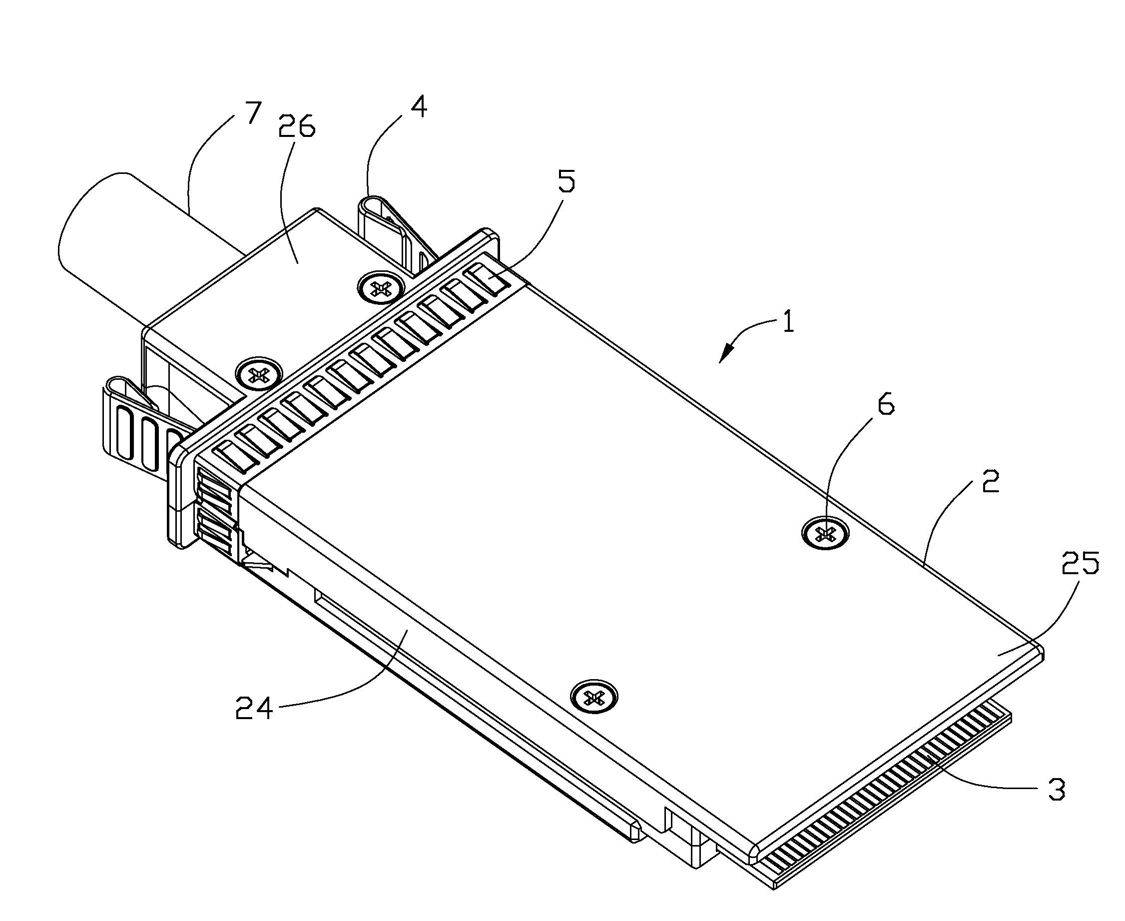
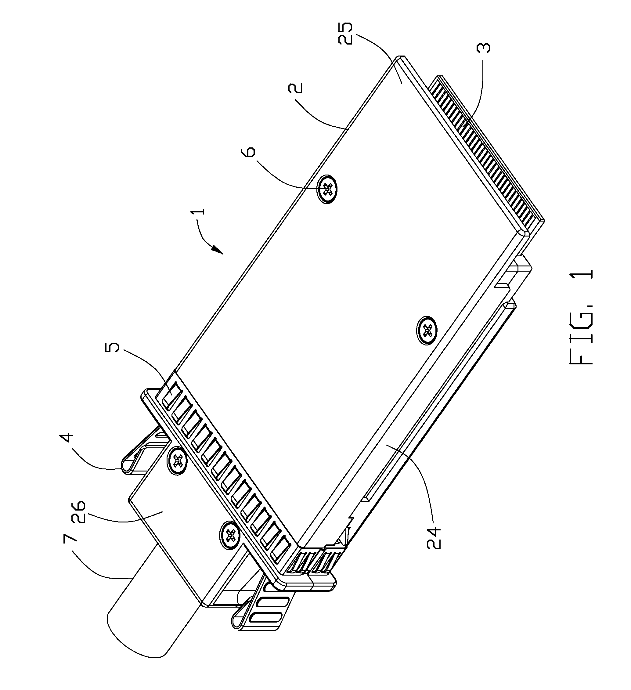
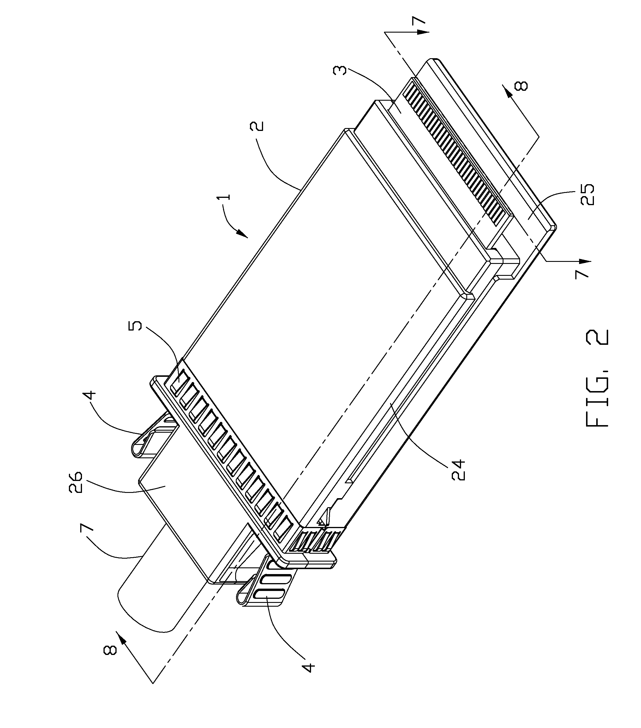
[0018]Referring to FIGS. 1, 2 and 5, an electrical connector assembly 1 in accordance with the present invention for electrically connected with a cable 7 or an optical module (not shown), comprises a metallic housing 2, a printed circuit board 3 disposed in the metallic housing 2, a pair of latches 4 located at two sides of the metallic housing 2 and a gasket 5 surrounding an outer surface of the metallic housing 2. A strain relief 8 is attached to a front end of the cable 7.

[0019]Referring to FIGS. 1 to 4 and 8, the metallic housing 2 includes a lower cover 21 and an upper cover 22 assembled to the lower cover 21. The lower cover 21 and upper cover 22 are all die-cast to provide EMI protection. The housing 2 defines a receiving room 23 for receiving a printed circuit board 3 and a front end of the cable 7, a front opening (not figured) for a mating portion 31 of the printed circuit ...


PUM


Abstract

An electrical connector assembly (1) for connecting with a cable (7), comprises a metallic housing (2) defining a receiving room (23), a pair of receiving spaces disposed at two sides of the receiving room and a pair of slits formed at two sides of the housing and respectively communicated with the pair of receiving spaces. A printed circuit board (3) is received into the receiving room and has a mating portion (31) extending forwardly from a front surface of the housing. A pair of latches (4) received into the corresponding receiving spaces, each latch having a base portion (41) disposed in the receiving space, an engaging portion (42) formed at a front end thereof and engaged with the housing and a pressing portion (43) extending rearwardly from the base portion and out of the housing, a latching portion (411) extending outwardly from the base portion and passing through the slit for latching with a complementary connector, an elastic portion (412) extending inwardly and rearwardly from the base portion to urge the latching portion extending out of the housing.

Description

FIELD OF THE INVENTION[0001]The present invention relates to an electrical connector assembly, and more particularly to an electrical connector assembly used for high-speed transmission.DESCRIPTION OF PRIOR ART[0002]SFP (Small Form-factor Pluggable), X-SFP and QSFP are all modules for fiber optic transmission or signal transmission. All of the modules are of small size or form factor which is important. The smaller the form factor of the module, the less space taken on a printed circuit board to which it couples. A smaller form factor allows a greater number of modules to be coupled onto a printed circuit board to support additional communication channels. However, the smaller form factor makes it more difficult for a user to handle.[0003]When such a module embedded in a system fails to work, it is desirable to replace it, particularly when other communication channels are supported by other modules. To replace a failed module, it needs to be pluggable into a module receptacle. Whil...

Claims


Application Information

Patent Timeline
IPC IPC(8): H01R13/627
CPCH01R9/03H01R13/6658H01R13/6275H01R13/512
Inventor WU, JERRY
Owner HON HAI PRECISION IND CO LTD
Why Eureka
Try Eureka