Snap together push button latch mechanism

a push button and latch mechanism technology, applied in the field of electronic devices, can solve the problems of increasing manufacturing time, complex mechanisms, time-consuming process, etc., and achieve the effect of facilitating the removal and installation of the cover of the device quickly and easily

Inactive Publication Date: 2008-07-17
IBM CORP
View PDF7 Cites 11 Cited by
  • Summary
  • Abstract
  • Description
  • Claims
  • Application Information

AI Technical Summary

Benefits of technology

[0009]As a result of the summarized invention, technically we have achieved an improved push button latch mechanism that is allows removal and installation of a cover for a device quickly and without the need for hand tools. Adoption of the latch mechanism does not require complex modifications to be made to the cover or to the device.

Problems solved by technology

This process can be time consuming and may require additional hand tools to accomplish the removal of the cover from the device.
Often these mechanisms are complex, requiring additional features to be added to the cover and the device in secondary manufacturing operations, which increases manufacturing time.
The incorporation of these features also often increases the complexity of the tooling used to mold the cover, which in turn can have a negative effect on product cost and quality.

Method used


Image

  • Snap together push button latch mechanism
  • Snap together push button latch mechanism
  • Snap together push button latch mechanism

Examples


Embodiment Construction

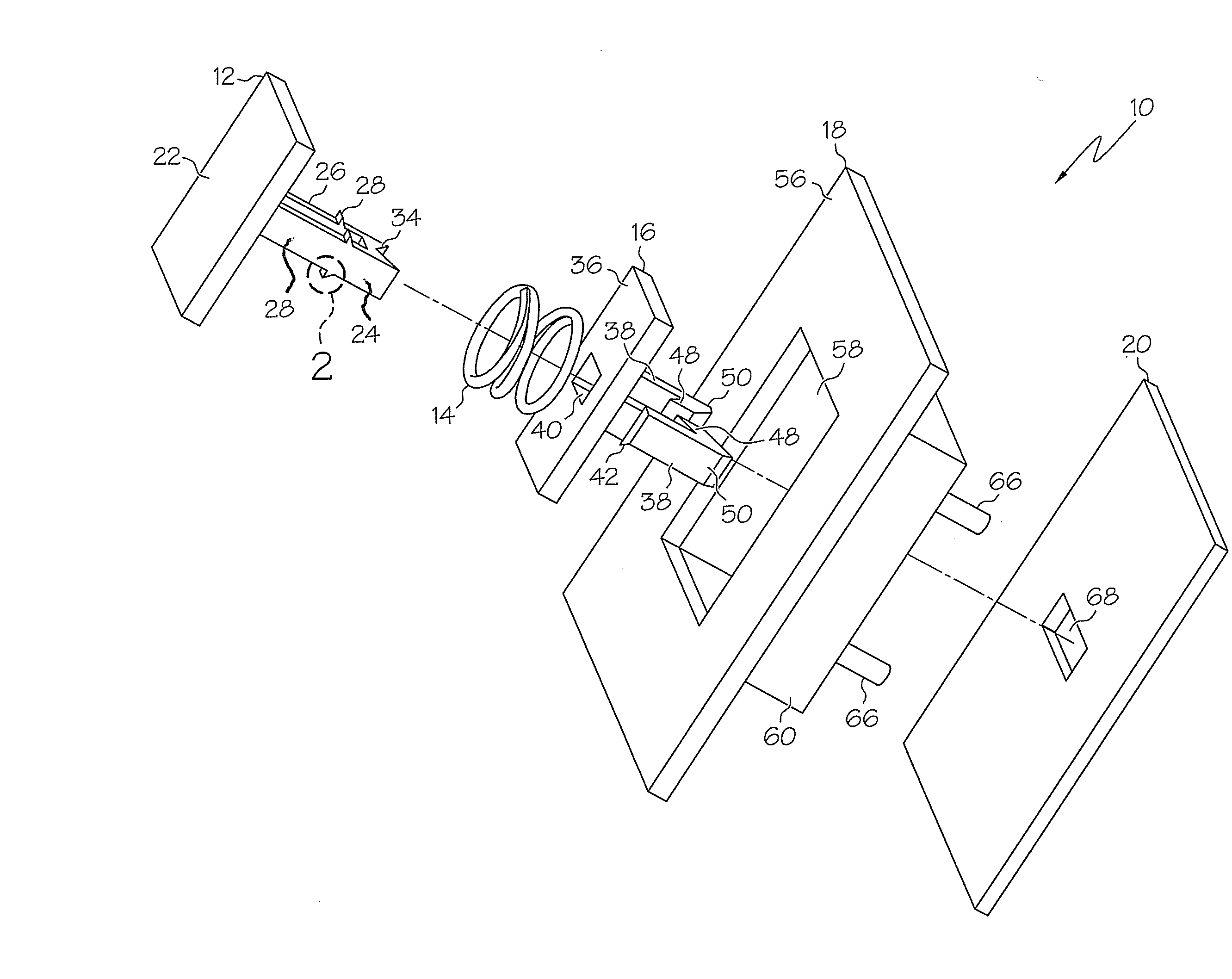
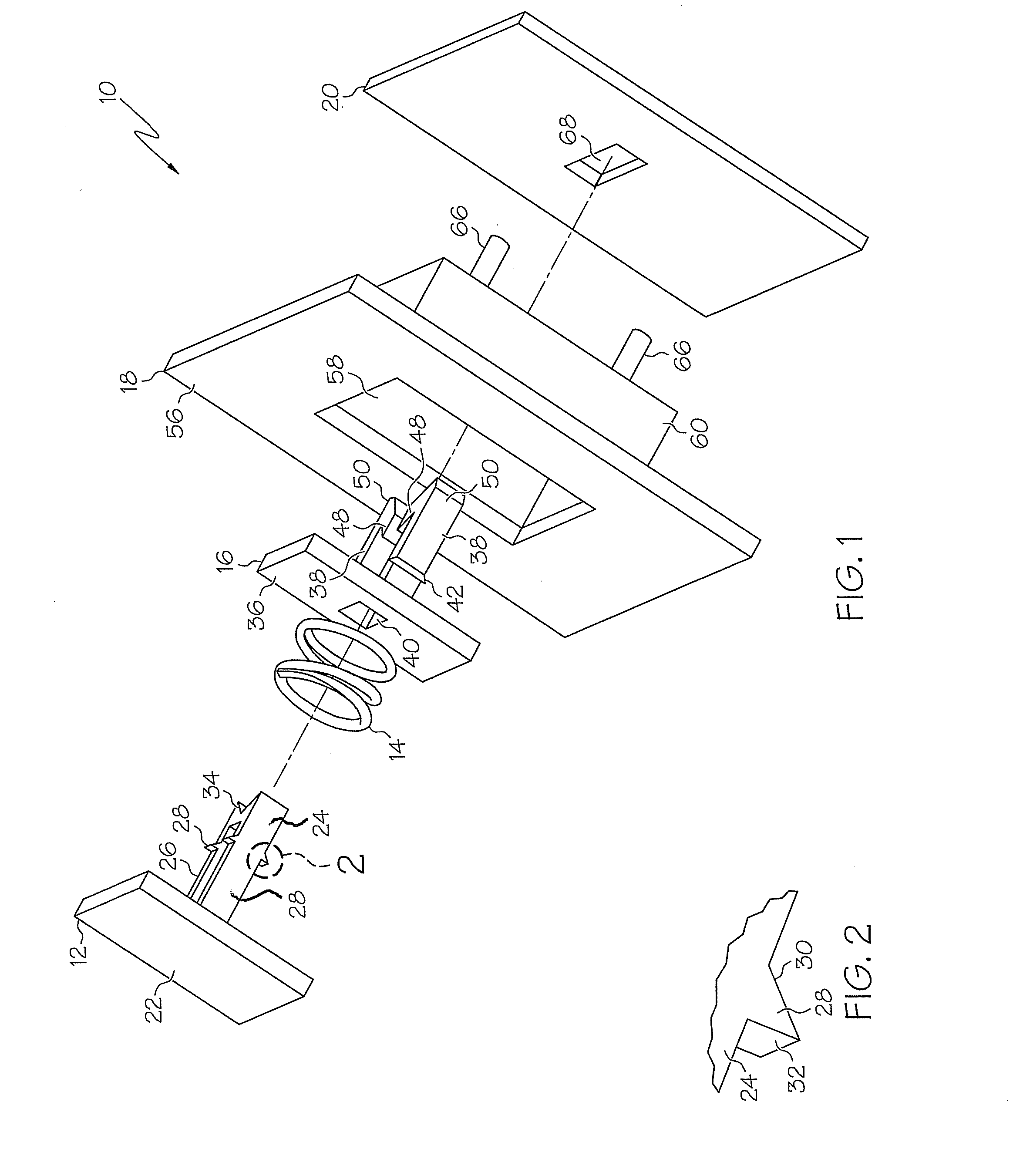
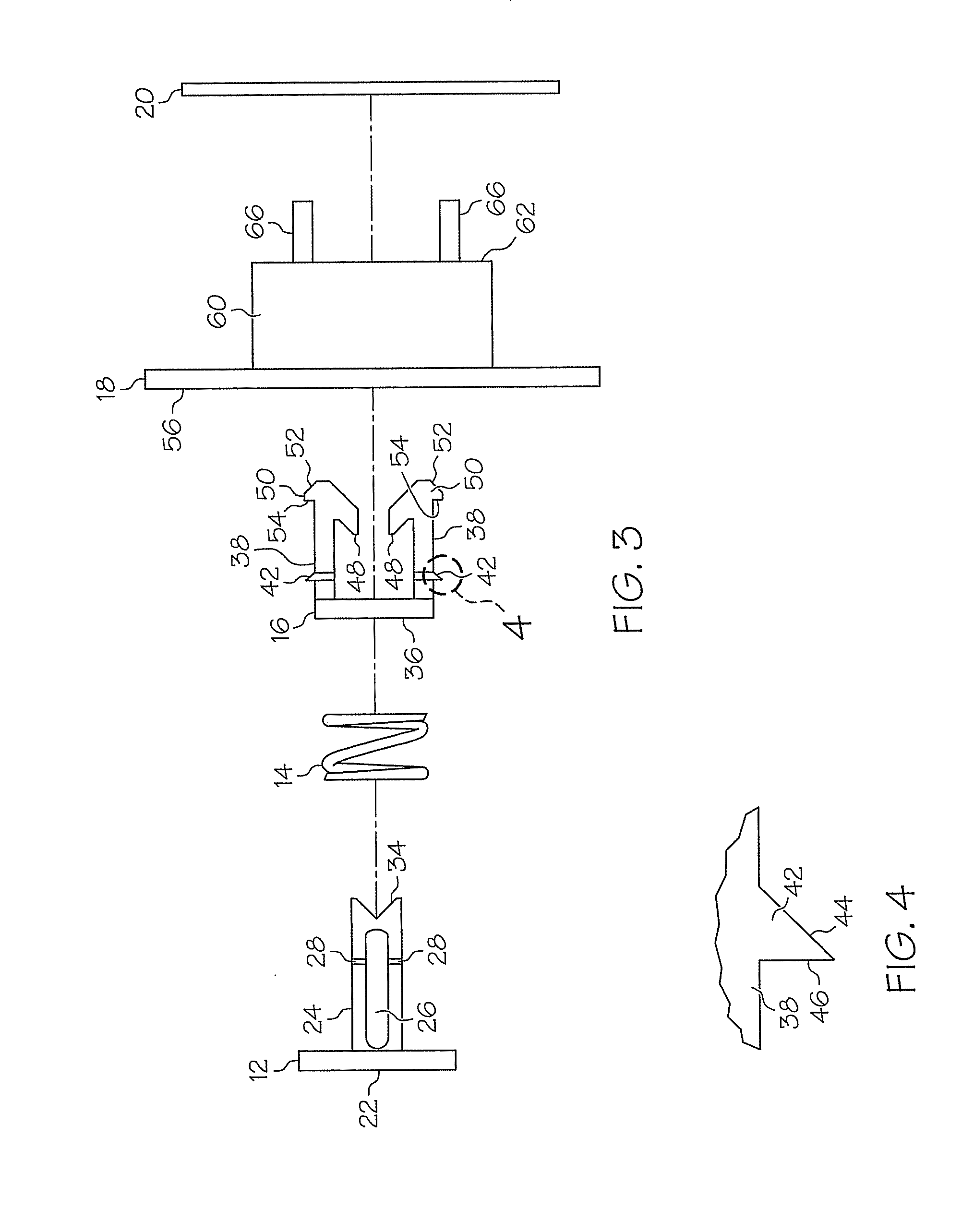
[0018]Turning now to the drawings in greater detail, it will be seen that in FIG. 1 there is an embodiment of an improved latch mechanism 10. The latch mechanism 10 comprises a plunger 12, a spring 14, and a catch 16, which secures a cover 18 to a device 20. It should be noted that any number of latch mechanisms 10 may be used to secure the cover 18 to the device 20. In the figures, the cover 18 and the device 20 are shown as partial views for clarity, isolating one securing point.

[0019]The plunger 12 may be formed from a plastic material and includes a plunger face 22, which in this embodiment has a rectangular shape. A plunger shaft 24 extends substantially from a center of the plunger face 22 and has a cross-section that is generally rectangular. The plunger shaft 24 may include a plunger cavity 26 that eliminates unnecessary material without negatively affecting the strength of the plunger shaft 24. The plunger shaft 24 includes plunger barbs 28 disposed on opposite sides of the...


PUM


Abstract

Disclosed is a push button latch mechanism including a catch, a spring, and a plunger. The catch includes two legs connected to a catch face. Each leg includes a first hook insertable through and retained in a hole in the structure, a second hook extending inward and toward the catch face from the free end, and a third hook insertable into and retained in a hole formed in the cover. The plunger includes a shaft having one or more tabs insertable into a hole in the catch face and retained by it, and a v-notch at the free end of the shaft configured to be accepted into the second hooks of the catch when the plunger is pushed, thereby forcing the legs of the catch closer together and releasing the first hooks from the hole in the structure allowing the cover to be removed. The spring is disposed around the shaft and configured such that when the plunger is released, the plunger returns to its original position.

Description

BACKGROUND OF THE INVENTION[0001]1. Field of the Invention[0002]This invention relates to electronics devices such as computers and the like. In particular, this invention relates to a push-button latch mechanism for securing a cover to the device.[0003]2. Description of Background[0004]Electronic devices such as computers, printers, and the like typically have covers that must be frequently removed and reinstalled. In many cases, the cover is attached to the electronic device using thumbscrews or the like which must unscrewed each time the cover is removed from the device. This process can be time consuming and may require additional hand tools to accomplish the removal of the cover from the device.[0005]The attachment of the cover to the device is often alternatively accomplished by quick-releasing latch mechanisms. Often these mechanisms are complex, requiring additional features to be added to the cover and the device in secondary manufacturing operations, which increases manufa...

Claims


Application Information

Patent Timeline
Patent Type & Authority Applications(United States)
IPC IPC(8): F16B13/06
CPCE05B15/102F16B21/075E05C19/022
Inventor BORAAS, MICHAEL A.
Owner IBM CORP
Why Eureka
Try Eureka