Latch control by gear position sensing

a technology of gear position and latch assembly, which is applied in the direction of electrical locking actuators, instruments, and sensor output conversion, etc., can solve the problems of difficult, but necessary, to control motors, including gears, within the vehicle latch assembly

Inactive Publication Date: 2008-01-17
CHEVALIER
View PDF47 Cites 4 Cited by
  • Summary
  • Abstract
  • Description
  • Claims
  • Application Information

AI Technical Summary

Benefits of technology

[0006]The following summary of the invention is provided to facilitate an understanding of some of the innovative features unique to the present invention and is not intended to be a full description. A full appreciation of the various aspects of the invention can be gained by taking the entire specification, claims, drawings, and abstract as a whole.
[0007]It is, therefore, one aspect of the present invention to provide for an improved latch mechanism.
[0008]It is another aspect of the present invention to provide for improved latching methods and systems for use in automobiles and other vehicles.
[0009]It is yet a further aspect of the present invention to provide for a geartooth sensor that provides data for the control of a vehicle door latch assembly.
[0010]The aforementioned aspects of the invention and other objectives and advantages can now be achieved as described herein. A latch assembly control method and system are disclosed herein, wherein a latch assembly is integrated with a motor having at least one gear thereof for actuating a plurality of components of the latch assembly. A geartooth sensor can be associated with the latch assembly, wherein the geartooth sensor senses a position of one or more gears, wherein the gear completes less than one revolution to thereby provide a known reference point registration and calibration of the latch assembly via data collected from the geartooth sensor.

Problems solved by technology

One of the problems inherent with conventional latching mechanisms is that it is difficult, but necessary, to control motors, including gears thereof, within vehicle latch assemblies.

Method used


Image

  • Latch control by gear position sensing
  • Latch control by gear position sensing
  • Latch control by gear position sensing

Examples


Embodiment Construction

[0020]The particular values and configurations discussed in these non-limiting examples can be varied and are cited merely to illustrate at least one embodiment of the present invention and are not intended to limit the scope of the invention.

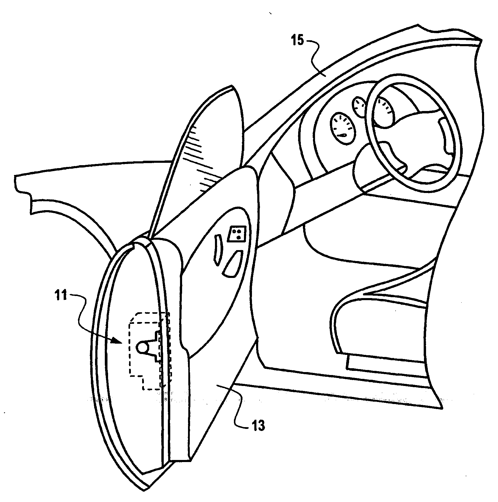
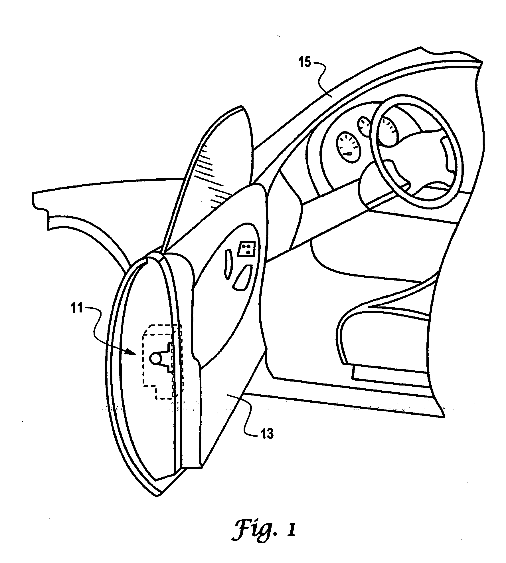
[0021]FIG. 1 illustrates a perspective view of a vehicle door 13 mounted to a passenger vehicle in which a preferred embodiment of the present invention can be implemented. A vehicle, such as an automobile can be equipped with one or more individual door latch assemblies 11, which secure respective passenger and driver side doors to the vehicle 15. Each door latch assembly 11 is typically provided with manual release mechanisms or lever for unlatching the door latch from the inside and outside of the vehicle, e.g. respective inner and outer door handles. In addition, many vehicles can also be equipped with electrically controlled actuators for remotely locking and unlocking the door latches. As indicated in FIG. 1, a door latch assembly 11 can ...


PUM


Abstract

A latch assembly control method and, wherein a latch assembly is integrated with a motor having at least one gear thereof for actuating a plurality of components of the latch assembly. A geartooth sensor can be associated with the latch assembly, wherein the geartooth sensor senses a position of one or more gears, wherein the gear completes less than one revolution to thereby provide a known reference point registration and calibration of the latch assembly via data collected from the geartooth sensor.

Description

TECHNICAL FIELD[0001]Embodiments are generally related to door latch assemblies, including door latching mechanisms utilized in automobiles and other vehicles. Embodiments are also related to geartooth sensor devices and techniques thereof.BACKGROUND OF THE INVENTION[0002]Latching mechanisms are utilized in a variety of commercial and industrial applications, such as automobiles, airplanes, trucks, and the like. For example, an automotive closure, such as a door for an automobile passenger compartment, is typically hinged to swing between open and closed positions and conventionally includes a door latch that is housed between inner and outer panels of the door. The door latch functions in a well-known manner to latch the door when it is closed and to lock the door in the closed position or to unlock and unlatch the door so that the door can be opened manually.[0003]The door latch can be operated remotely from inside the passenger compartment by two distinct operators—a sill button ...

Claims


Application Information

Patent Timeline
Patent Type & Authority Applications(United States)
IPC IPC(8): E05C3/06
CPCE05B81/06G01D5/147E05B81/34E05B81/64G01D5/2451Y10T292/1047
Inventor CHEVALIER, JOHN PHILLIP
Owner CHEVALIER
Why Eureka
Try Eureka