Security and identification tags

Inactive Publication Date: 2009-09-24
TAG UK
View PDF6 Cites 3 Cited by
  • Summary
  • Abstract
  • Description
  • Claims
  • Application Information

AI Technical Summary

Benefits of technology

[0009]By providing the loop antenna with a substantially triangular shape, it is possible to position the tag on CD or DVD packaging (which is typically square or rectangular) in a cor

Problems solved by technology

One problem encountered with such devices when used on cases for CDs, DVDs, and Video Games is that the metallization layer on the disc interferes with the RF signals, reducing the power and range available.
This problem is particularly evident at certain frequencies when the loop antenna

Method used


Image

  • Security and identification tags
  • Security and identification tags
  • Security and identification tags

Examples


Example

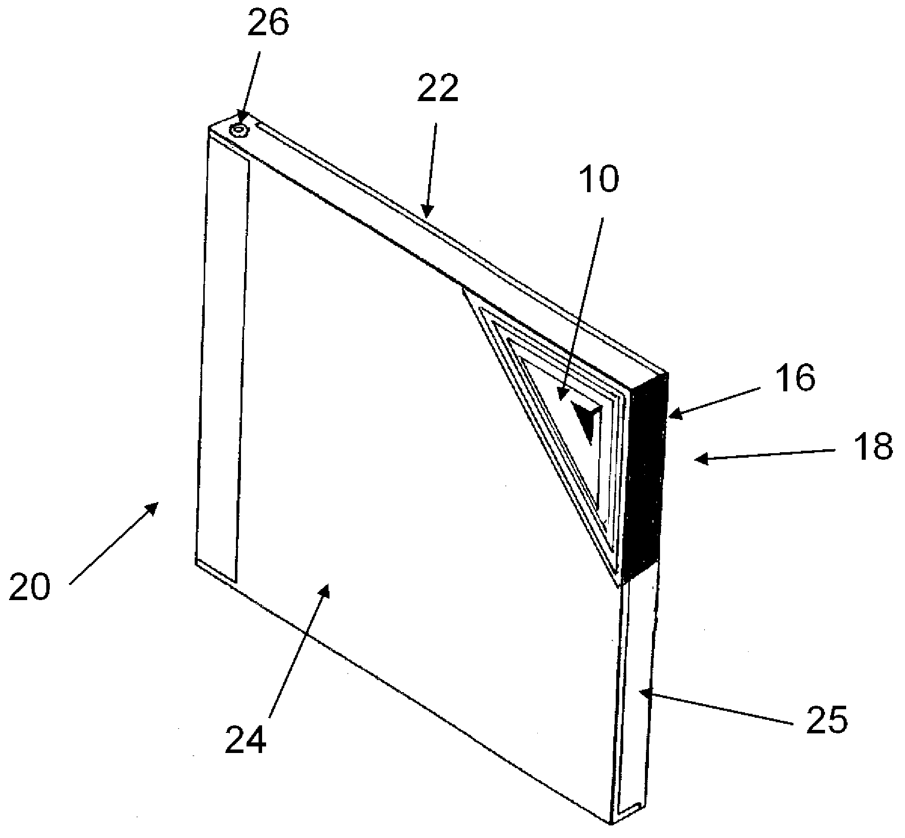
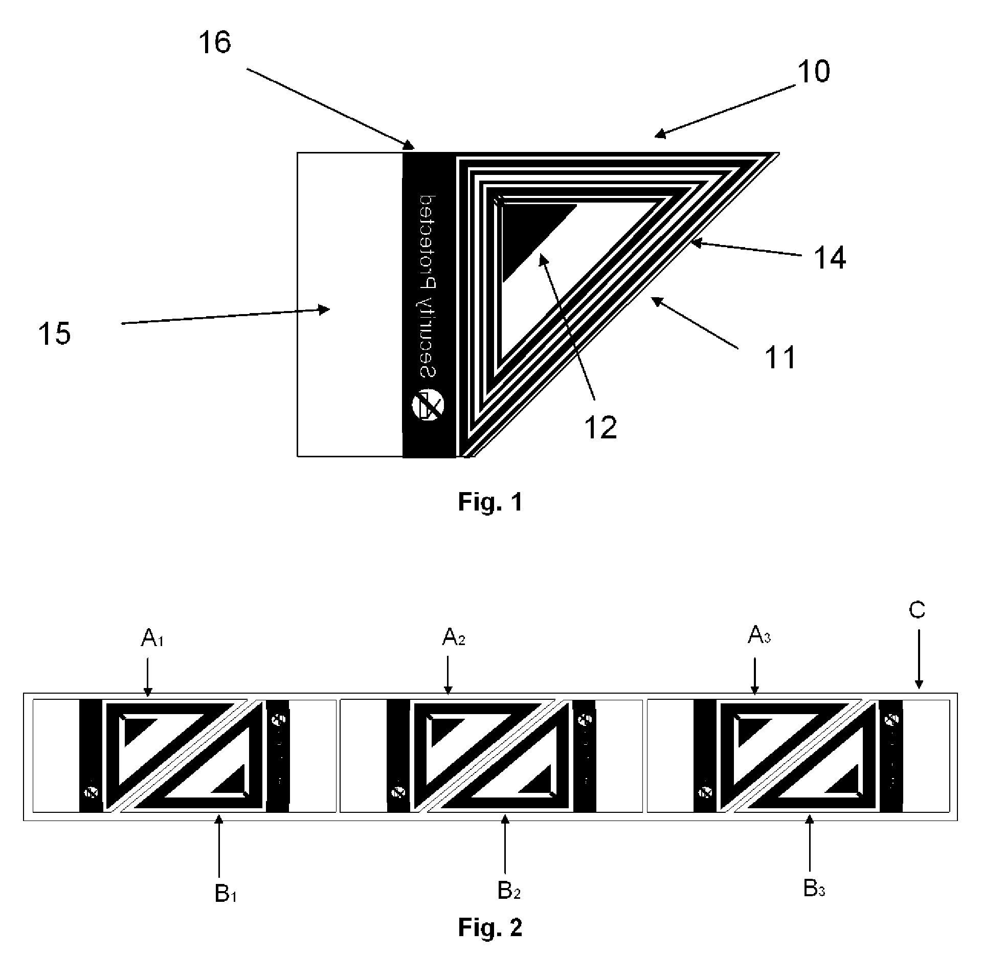
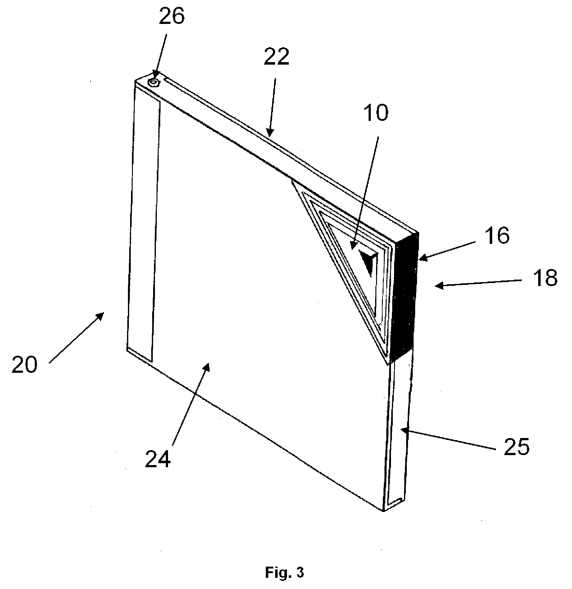
[0017]FIG. 1 shows one embodiment of an EAS tag according to the invention. The active part of the tag 10 comprises a loop antenna 11 in the form of a triangle, and an electronic component 12 connected to the antenna 11 and located within the loop. The active part 10 is formed from thin, flexible metallic structures, typically aluminium, disposed on one face of a flexible substrate 14. The manner of forming such flexible structures on substrates is well-known for use in identification tag devices. The flexible substrate 14 is a clear plastic material. In the region of the active part 10, the substrate 14 has a corresponding, but slightly larger, triangular shape. The part of the substrate 14 along one of the sides of the antenna 11 is extended to form a flap 15. A printed section 16 is provided on the substrate adjacent the same side of the antenna 11. This printed section 16 can carry security markings, branding or any other information.

[0018]The face of the substrate 14 opposite t...


PUM


Abstract

An identification tag, such as an EAS tag or an RFID tag, comprising a loop antenna having a substantially triangular shape and an electronic component connected to and positioned within the loop antenna, the antenna and component comprising a flexible metal structure disposed on one face of a flexible substrate, the flexible substrate extending away from one side of the triangular loop antenna to form a flap such that, when the tag is positioned on a face of a package close to its edge, the flap can be wrapped around the edge of the package and onto its other face.

Description

TECHNICAL FIELD[0001]This invention relates to security tags that can be applied to articles for theft prevention, inventory tracking, etc. Such tags includes radio-frequency and magnetic EAS (electronic article surveillance) tags, radio-frequency identification (RFID) tags, and the like. In particular, the invention relates to such tags that are suitable for use on items such as cases for compact discs (CDs), digital versatile discs (DVDs), Video Games, and the like. The term ‘security tag’ is used here for both EAS and RFID tags.BACKGROUND ART[0002]EAS tags are well-known as anti-theft devices. Radio-frequency EAS tags essentially comprise an LC tank circuit with a resonance peak at a predetermined frequency. Detection is achieved by sweeping an rf field around the predetermined frequency and detecting a dip due to the presence of the tag. The tags are deactivated by submitting them to a strong FM field to induce voltages exceeding the capacitor's breakdown voltage.[0003]One commo...

Claims


Application Information

Patent Timeline
IPC IPC(8): H04B7/00H01Q11/12G06K19/04G06K19/077
CPCG06K19/04G06K19/07749G09F3/0335G06K19/07771G06K19/07758
Inventor CONNELL, SUZANNE REBECCAKROM, MARK DANIELMARCHESE, JONATHAN PETER
Owner TAG UK
Why Eureka
Try Eureka