Discharge lamp lighting device, control method for the same, and projector

a technology for lighting devices and discharge lamps, which is applied in the direction of electric variable regulation, process and machine control, instruments, etc., can solve the problems of shortening the life reducing the luminance of the discharge lamp, and changing the shape of the electrodes, so as to reduce heat load and reduce flicker. occurrence

Active Publication Date: 2009-09-24
SEIKO EPSON CORP
View PDF5 Cites 21 Cited by
  • Summary
  • Abstract
  • Description
  • Claims
  • Application Information

AI Technical Summary

Benefits of technology

[0007]An advantage of some aspects of the invention is that a discharge lamp lighting device, a control method for the same, and a projector can be provided which enable restraining occurrence of flicker while reducing heat load on a discharge lamp electrode.

Problems solved by technology

In such a discharge lamp, wear of electrodes due to discharge causes change in the shape of the electrodes.
These phenomena cause reduction in luminance of the discharge lamp and shorten the life of the discharge lamp.
This is not desirable.
When the variation range of pulse width modulation is set to be large enough to sufficiently melt a protrusion grown at the distal end of an electrode, excessive heat load is applied to an electrode having no protrusion grown at its distal end, and this accelerates wear of the electrode.
On the contrary, when pulse width modulation is carried out to such an extent that excessive heat load is not applied to the electrode having no protrusion grown at its distal end, if the protrusion at the distal end of the electrode becomes harder to melt because of increase in cumulative lighting time of the electrode and so on, the unwanted protrusion on the electrode cannot be melted, thus making it difficult to sufficiently restrain occurrence of flicker.

Method used


Image

  • Discharge lamp lighting device, control method for the same, and projector
  • Discharge lamp lighting device, control method for the same, and projector
  • Discharge lamp lighting device, control method for the same, and projector

Examples


first embodiment

2. Discharge Lamp Lighting Device

(1) Exemplary Circuit Configuration of Discharge Lamp Lighting Device

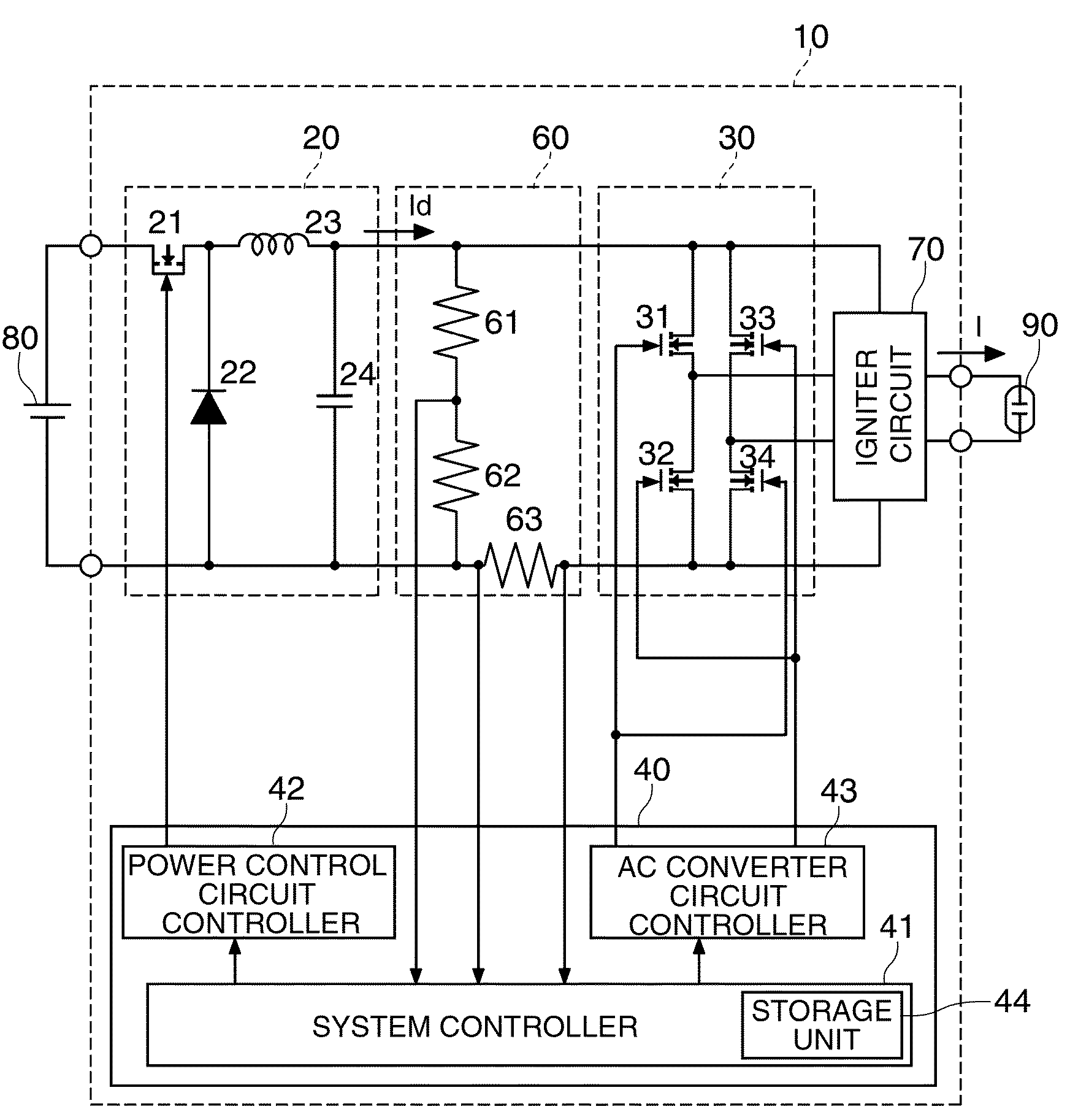
[0063]FIG. 3 shows an exemplary circuit diagram of the discharge lamp lighting device according to this embodiment.

[0064]The discharge lamp lighting device 10 includes a power control circuit 20. The power control circuit 20 controls driving power supplied to the discharge lamp 90. In this embodiment, the power control circuit 20 is formed by a down chopper circuit that takes a DC power source 80 as its input, then lowers the input voltage and outputs a DC current Id.

[0065]The power control circuit 20 may include a switch element 21, a diode 22, a coil 23 and a capacitor 24. The switch element 21 may be formed, for example, by a transistor. In this embodiment, one end of the switch element 21 is connected to the positive voltage side of the DC power source 80 and the other end is connected to the cathode terminal of the diode 22 and one end of the coil 23. Moreover, one end of the c...

second embodiment

3. Discharge Lamp Lighting Device

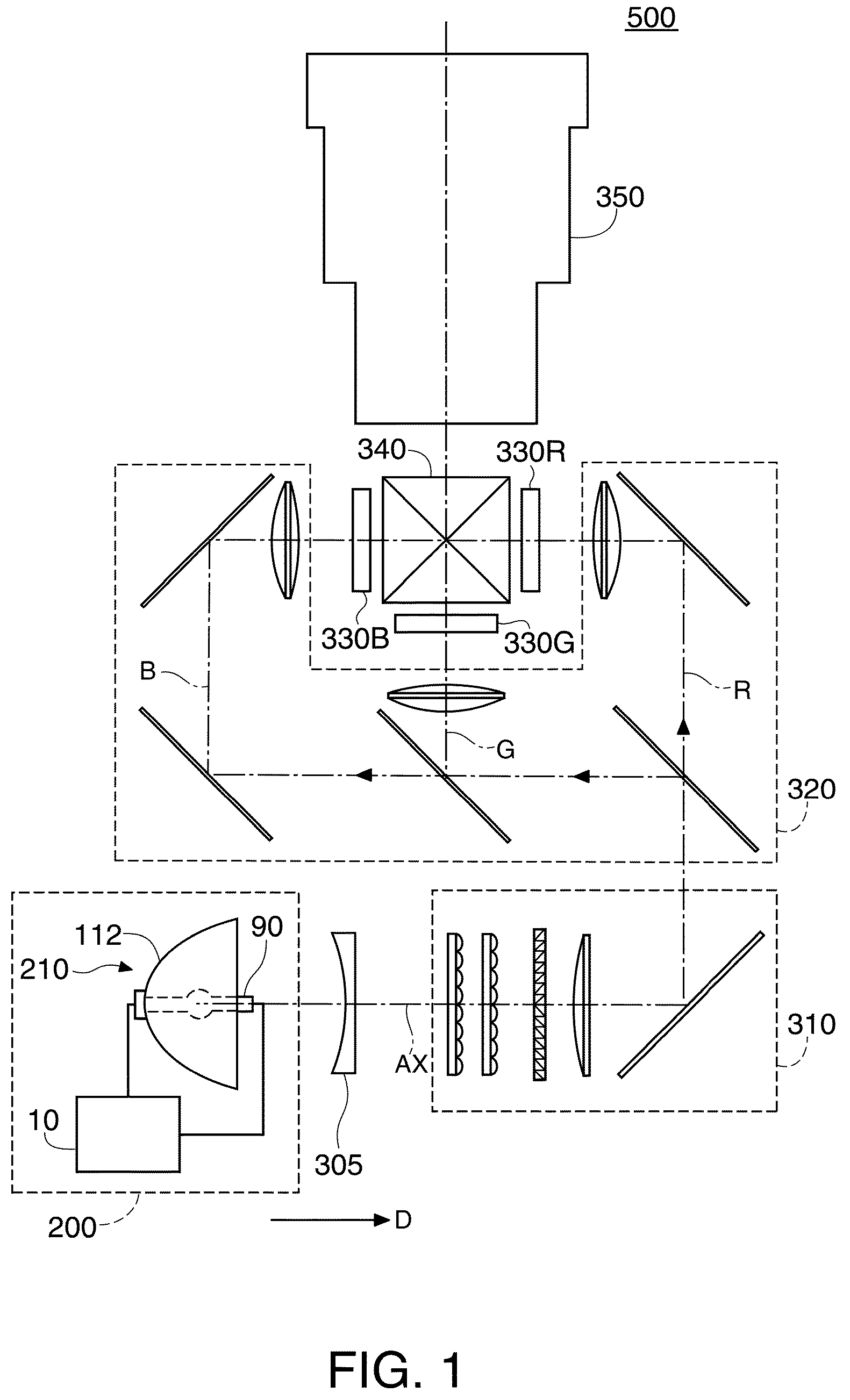
[0154]The case of controlling the cumulative energy supplied to each electrode in one cycle of the AC current I for discharge lamp driving by using the current value of the AC current I for discharge lamp driving will now be described with reference to FIG. 1 to FIGS. 4A-4D and FIG. 12 to FIG. 17. The elements of configuration similar to those of the first embodiment are denoted by the same reference numerals and will not be described further in detail.

[0155]In this case, the control unit 40 carries out repair control to perform sectional current control processing to change, in a cyclical pattern, the difference in absolute value between the current value of the AC current I for discharge lamp driving in the first polarity section and the current value in the second polarity section. This cyclical pattern includes plural sectional periods in which the difference in absolute value between the current value in the first polarity section and the curren...

first modification

[0176]In the above embodiment, the control unit 40 carries out control with the fixed difference in absolute value between the current value of the AC current I for discharge lamp driving in the first polarity section and the current value in the second polarity section, in other times than repair control. However, the control unit 40 may carry out stationary control to control the difference in absolute value between the current value of the AC current I for discharge lamp driving in the first polarity section and the current value in the second polarity section in a different cyclical pattern from the above pattern, in other times than repair control. In such case, at the time of repair control, the control unit 40 may carry out control with a cyclical pattern in which the difference between the maximum value and the minimum value of the difference in absolute value between the current value of the AC current I for discharge lamp driving in the first polarity section and the curre...


PUM


Abstract

A discharge lamp lighting device includes: a power control circuit that outputs a DC current; an AC converter circuit that takes the DC current as its input, inverts polarity of the DC current between first polarity and second polarity in predetermined timing, and thereby generates and outputs an AC current for discharge lamp driving; and a control unit that carries out AC conversion control processing to the AC converter circuit to control polarity inversion timing of the AC current for discharge lamp driving, and current control processing to the power control circuit to control a current value of the DC current. The control unit carries out repair control to change, in a first cyclical pattern, cumulative energy supplied to each electrode of a discharge lamp during one cycle of the AC current for discharge lamp driving, in predetermined timing. The first cyclical pattern includes plural sectional periods in which the cumulative energy is maintained at the same value over plural cycles of the AC current for discharge lamp driving. The cumulative energy differs between at least two of the sectional periods.

Description

BACKGROUND[0001]1. Technical Field[0002]The present invention relates to a discharge lamp lighting device, a control method for the same, and a projector.[0003]2. Related Art[0004]As a light source of a projector, a discharge lamp such as a high-pressure mercury lamp or metal halide lamp is used. In such a discharge lamp, wear of electrodes due to discharge causes change in the shape of the electrodes. If plural protrusions are grown at the distal end of the electrodes or irregular wear of the electrode bodies progresses, shift of arc starting point and change in arc length occur. These phenomena cause reduction in luminance of the discharge lamp and shorten the life of the discharge lamp. This is not desirable.[0005]As a method to address this problem, U.S. Pat. No. 6,815,907 proposes a technique of pulse width modulation with the absolute value of an AC current for discharge lamp driving maintained substantially at a constant level.[0006]However, in U.S. Pat. No. 6,815,907, pulse ...

Claims


Application Information

Patent Timeline
Patent Type & Authority Applications(United States)
IPC IPC(8): G03B21/20H05B41/16
CPCH05B41/2928H05B41/3928Y02B20/202Y10S315/07G03B21/2026G03B21/2053Y02B20/208Y02B20/00
Inventor SOMA, SHIGEYASUYAMAUCHI, KENTARO
Owner SEIKO EPSON CORP
Why Eureka
Try Eureka