
Radio equipment control, radio equipment and communication system

a radio equipment and communication system technology, applied in the direction of substation equipment, electrical equipment, wireless network protocols, etc., can solve the problems of difficult to add and delete radio equipment to and from the cascade connection

Inactive Publication Date: 2009-09-24
FUJITSU LTD
View PDF6 Cites 20 Cited by
  • Summary
  • Abstract
  • Description
  • Claims
  • Application Information

AI Technical Summary

Benefits of technology

[0007]However, in order to perform communications between REC and RE in the conventional cascade connection, it is desired to be recognized in advance how REs are ca

Problems solved by technology

Therefore, it is difficult to newly add and delete any radio equipment to and from the cascade connection.

Method used


Image

  • Radio equipment control, radio equipment and communication system
  • Radio equipment control, radio equipment and communication system
  • Radio equipment control, radio equipment and communication system

Examples


Embodiment Construction

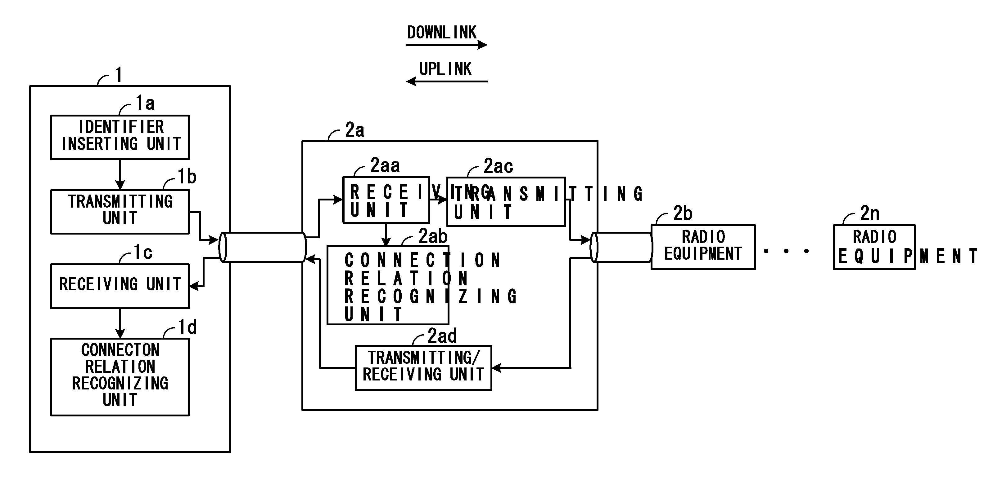
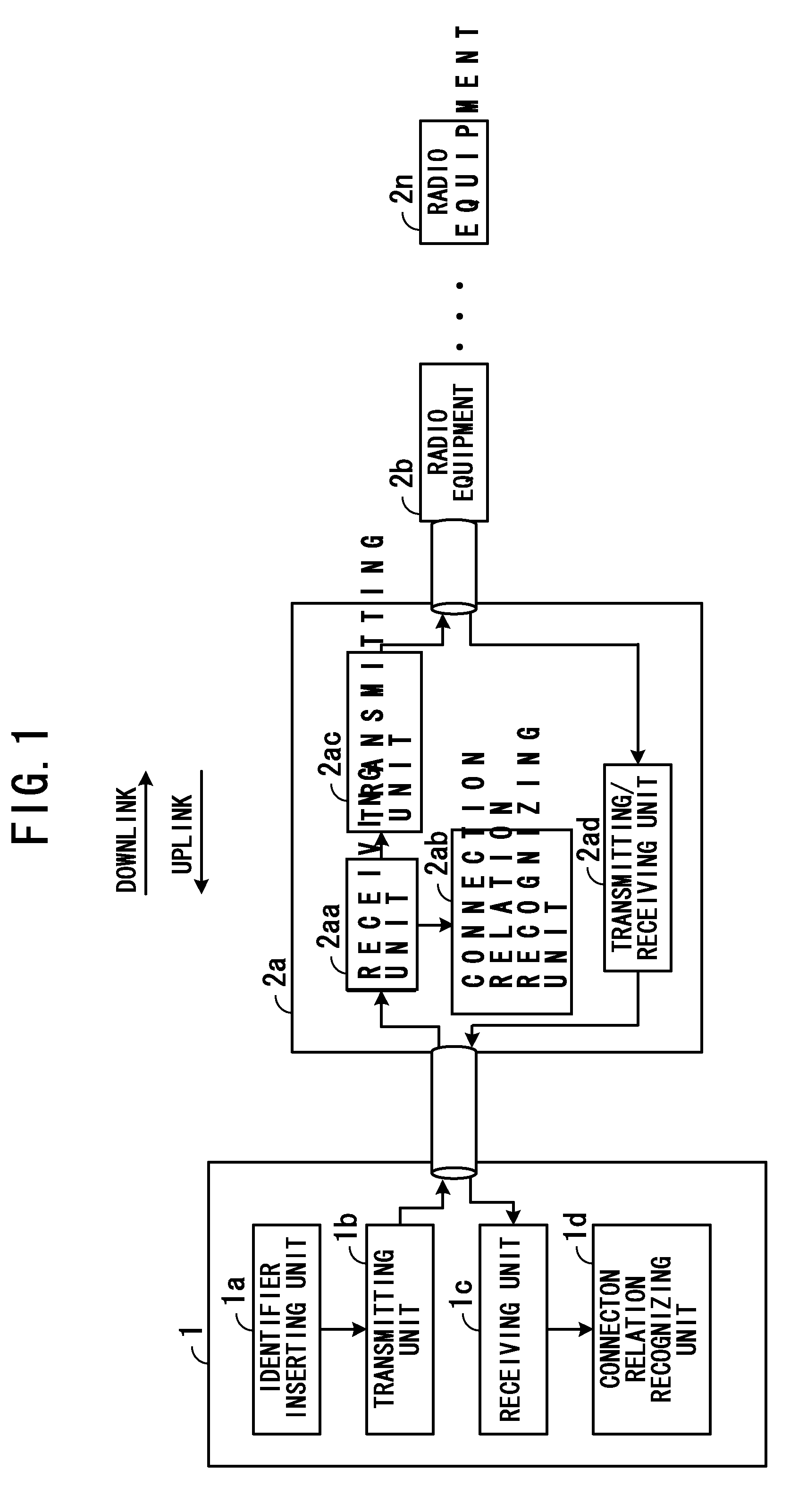
[0032]FIG. 1 is a diagram illustrating a radio equipment control and radio equipment units. A radio equipment control 1 and radio equipment units 2a, 2b, . . . , 2n illustrated in FIG. 1 are contained in a base station for wirelessly communicating with mobile terminals, such as cellular phones or the like.

[0033]The radio equipment control 1 and the radio equipment 2a, 2b, . . . , 2n are respectively adapted to recognize the cascade connection relation of the respective elements, and thus communicate with one another even when radio equipment is newly added to or deleted from the cascade connection of the radio equipment units 2a, 2b, . . . , 2n.

[0034]The radio equipment control 1 has an identifier inserting unit 1a, a transmitting unit 1b, a receiving unit 1c and a connection relation recognizing unit 1d. The radio equipment 2a has a receiving unit 2aa, a connection relation recognizing unit 2ab, a transmitting unit 2ac and a transmitting / receiving unit 2ad. The radio equipment uni...


PUM


Abstract

A radio equipment control for communicating plural radio equipment units including an identifier inserting unit for inserting into a frame an identifier for recognizing a connection relation of plural cascade-connected radio equipment units and a transmitting unit for transmitting the frame having the identifier inserted therein by the identifier inserting unit to the plural cascade-connected radio equipment units. The wireless communication apparatus includes a receiving unit for receiving the frame having the identifier inserted therein from the plural cascade-connected radio equipment units and a connection relation recognizing unit for recognizing the connection relation of the plural cascade-connected radio equipment units on the basis of the identifier of the frame received by the receiving unit.

Description

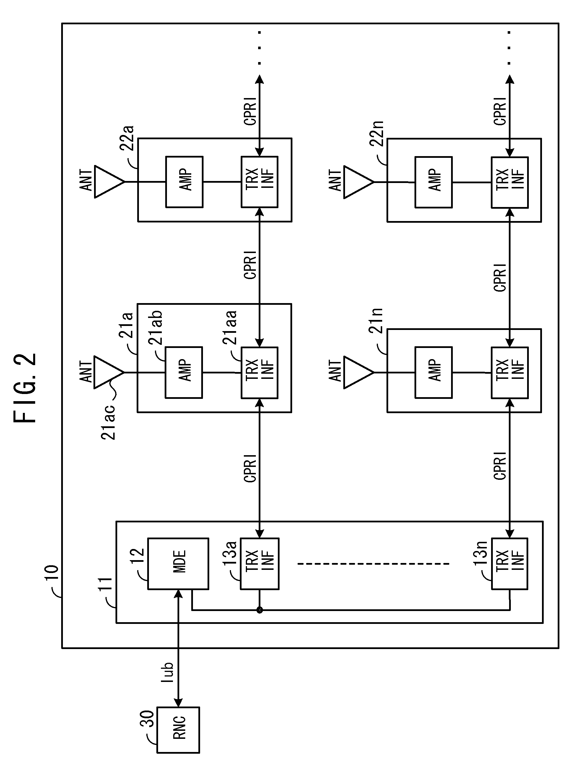
CROSS-REFERENCE TO RELATED APPLICATION(S)[0001]This application is based upon and claims the benefit of priority of the prior Japanese Patent Application No. 2008-72329, filed Mar. 19, 2008, the entire contents of which are incorporated herein by reference.BACKGROUND[0002]1. Field[0003]The present invention relates to a radio equipment control, radio equipment and a communication system to perform communications in a base station.[0004]2. Description of the Related Art[0005]A base station in a radio communication system that includes cellular phones or the like may be divided into RE (Radio Equipment), which processes radio signals, and REC (Radio Equipment Control), which controls the REs (RE units). For example, CPRI (Common Public Radio Interface) is known as an interface for connecting REC and REs. By using CPRI, the base station can be divided into REs and REC, and setting the interface is made open to users, whereby respective sections in the base station can be multivendored....

Claims


Application Information

Patent Timeline
IPC IPC(8): H04B7/00
CPCH04W8/26H04W88/085H04W80/02
Inventor YAMAMOTO, MASAKI
Owner FUJITSU LTD
Learn More