Dual-cavity fluid conveying apparatus

Inactive Publication Date: 2009-10-01
MICROJET TECH
View PDF3 Cites 6 Cited by
  • Summary
  • Abstract
  • Description
  • Claims
  • Application Information

AI Technical Summary

Benefits of technology

[0009]The object of the present invention is to provide a dual-cavity fluid conveying apparatus characterized in employing a flow-converging device to integrate two sets of fluid conveying cavities into one set thereof. In other words, the first cavity body and the second cavity body are mirror symmetrically disposed at a first side a

Problems solved by technology

Therefore, how to breakthrough technological bottlenecks by a creative technology turns out to be a significant issue of developments presently.
However, such as manner of connection of multiple micropump structures

Method used


Image

  • Dual-cavity fluid conveying apparatus
  • Dual-cavity fluid conveying apparatus
  • Dual-cavity fluid conveying apparatus

Examples


Example

[0030]Exemplified embodiments realizing the features of the present invention will be described in detail hereafter. It should be understood that a variety of modifications, made in various modes and not away from the scope of the present invention, is possible. The following description and drawings are essentially for the purpose of explaining, but not for limiting the present invention.

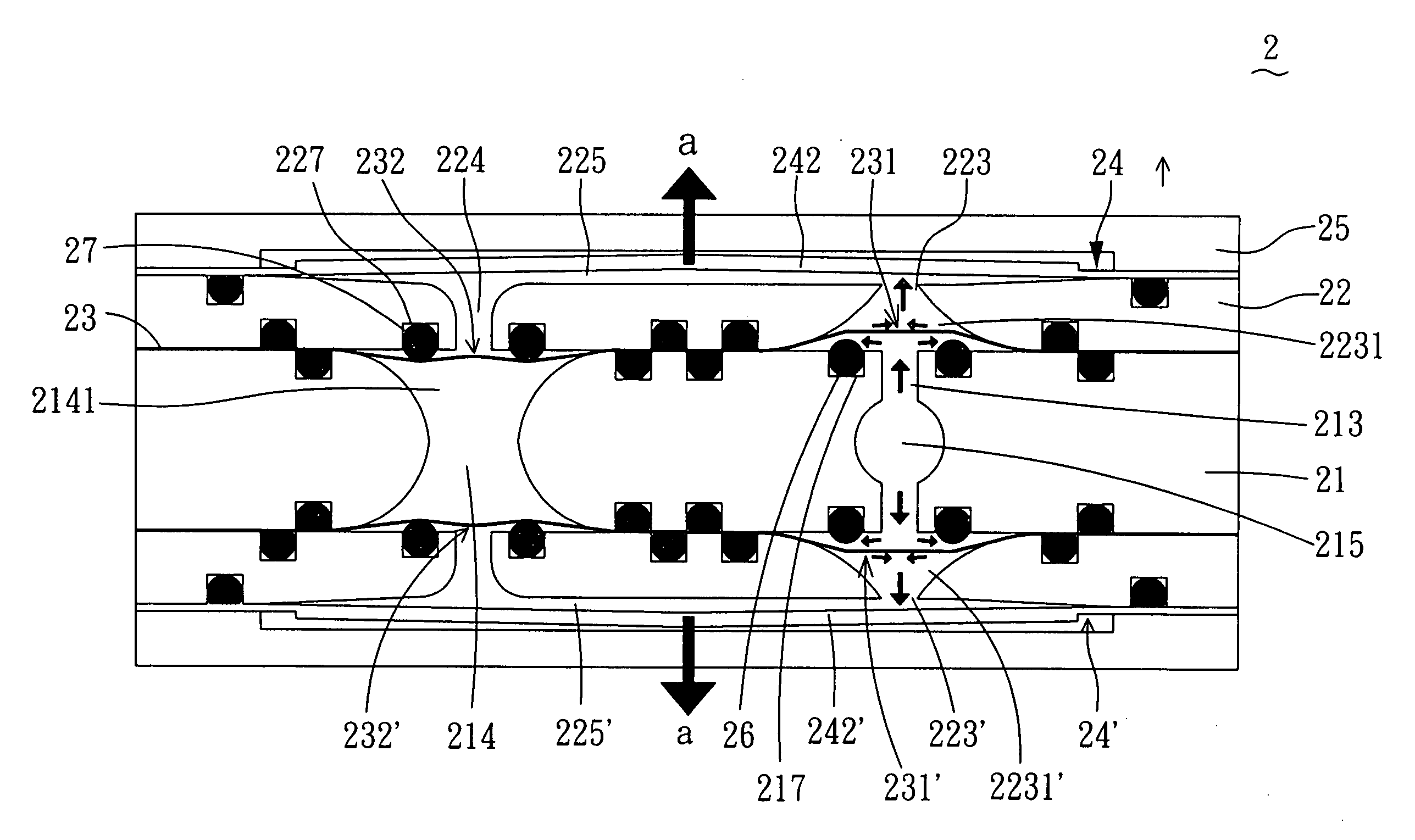
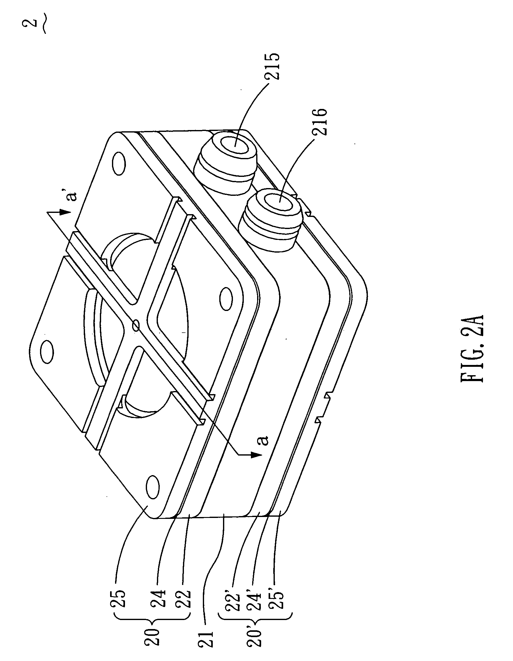
[0031]According to the present invention, the dual-cavity fluid conveying apparatus 2 can be employed in the industrial fields including, among others, medicine, biotechnology, energy, computer technology, and printing for the purpose of gas or fluid conveyance, but not limited to the fields listed above. Referring to FIGS. 2A and 2B, a perspective view and an exploded view illustrating a dual-cavity fluid conveying apparatus according to the present invention, the dual-cavity fluid conveying apparatus 2 comprises a first cavity body 20, a second cavity body 20′, and a flow-converging device 21. Th...


PUM


Abstract

A dual-cavity fluid conveying apparatus includes a flow-converging device, a first cavity body, and a second cavity body. The flow-converging device includes two sides corresponding to each other; a first channel and a second channel both passing through the two sides; and an inlet passage and an outlet passage both arranged between the two sides and communicated with the first channel and the second channel, respectively. The first cavity body and the second cavity body are symmetrically disposed at the two sides of the flow-converging device, wherein the first cavity body and the second cavity body each includes a valve cover disposed on one side of the flow-converging device, a valve membrane interposed between the one side of the flow-converging device and the valve cover, and an actuating device disposed circumferentially on the valve cover so as to define, together with the valve cover, a pressure chamber.

Description

BACKGROUND OF THE INVENTION[0001]1. Field of the Invention[0002]The present invention relates to a fluid conveying device, and more particularly, to a dual-cavity fluid conveying apparatus.[0003]2. Description of Related Art[0004]In following advancement of technologies, various fields, such as medicine, energy, computer technology, and printing are developed toward compact-size and mirco-size. As far as micropumps, sprayers, ink-jet printheads, or industrial printing devices are concerned, a fluid conveying apparatus involved therein is considered a key technique. Therefore, how to breakthrough technological bottlenecks by a creative technology turns out to be a significant issue of developments presently.[0005]Referring to FIG. 1, an exploded view illustrating a conventional micropump structure, the micropump structure 1 comprises a valve seat 11, a valve cover 12, a valve membrane 13, an actuating device 14, and a pump cover 15. The valve membrane 13 includes an inlet valve struc...

Claims


Application Information

Patent Timeline
IPC IPC(8): B81B7/00F15C3/00
CPCF04B53/106F04B45/04F04B43/043F04B53/1062Y10T137/2213Y10T137/2224
Inventor CHEN, SHIH CHANGCHANG, YING LUNYU, RONG HOCHIU, SHIH CHECHOU, TSUNG PAT
Owner MICROJET TECH
Why Eureka
Try Eureka