Electronic locking differential with direct locking state detection system

a technology of electronic locking differential and detection system, which is applied in the direction of mechanical actuated clutches, transportation and packaging, and gearing

Active Publication Date: 2009-10-01
AMERICAN AXLE & MFG
View PDF86 Cites 11 Cited by
  • Summary
  • Abstract
  • Description
  • Claims
  • Application Information

AI Technical Summary

Problems solved by technology

While such electronic locking differentials are fit for their intended purposes, they are nonetheless susceptible to improvement.

Method used


Image

  • Electronic locking differential with direct locking state detection system
  • Electronic locking differential with direct locking state detection system
  • Electronic locking differential with direct locking state detection system

Examples


Embodiment Construction

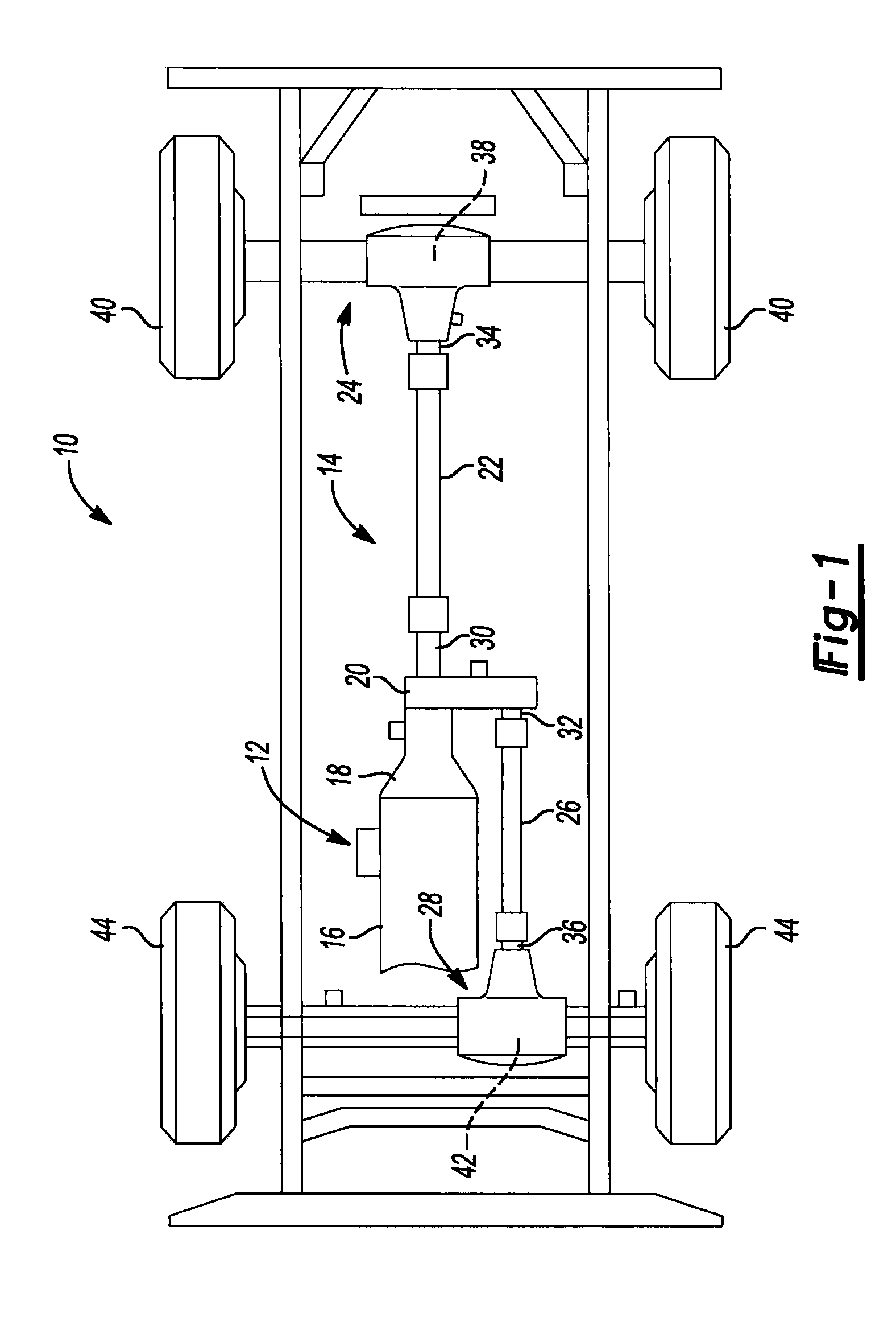
[0015]With reference to FIG. 1 of the drawings, an exemplary vehicle 10 is schematically shown and can include a power train 12 and a drive train 14. The power train 12 can include a power source, such as an internal combustion engine 16 and a transmission 18 that can receive rotary power from the engine 16 and output power to the drive train 14. The drive train 14 can include a transfer case 20, a rear propeller shaft 22, a rear axle assembly 24, a front propeller shaft 26 and a front axle assembly 28. The transfer case 20 can be employed to transmit drive torque from the transmission 18 to the rear and front axle assemblies 24 and 28. The transfer case 20 can include an input shaft (not specifically shown), which can be coupled to the transmission 18 to receive rotary power therefrom, a rear output shaft 30, which can be coupled to the rear propeller shaft 22, and a front output shaft 32 that can be coupled to the front propeller shaft 26. The rear propeller shaft 22 can transmit ...


PUM


Abstract

An axle assembly with an electronic locking differential that employs a locking mechanism having components that are fixed to one another along an axis such that they co-translate with one another when the actuator that effects the locking and unlocking of the differential is operated.

Description

[0001]This application is a continuation of U.S. application Ser. No. 11 / 700,564 filed Jan. 31, 2007, the disclosure of which is hereby incorporated by reference as if fully set forth in detail herein.INTRODUCTION[0002]The present disclosure generally relates to axle assemblies and more particularly to an axle assembly having an electronic locking differential.[0003]Commonly owned U.S. Pat. No. 6,958,030 discloses an electromagnetic locking differential assembly that employs an electromagnetic actuator to selectively couple a side gear to a differential case to cause the differential assembly to operate in a fully locked condition. More specifically, the electromagnetic actuator is actuated to axially translate an actuating ring (which is non-rotatably coupled to the differential case) such that dogs on the actuating ring matingly engage dogs that are formed on a face of the side gear opposite the gear teeth. While such electronic locking differentials are fit for their intended pur...

Claims


Application Information

Patent Timeline
Patent Type & Authority Applications(United States)
IPC IPC(8): F16H48/24B60K17/16F16H48/00
CPCB60K23/04F16H48/08F16H48/24F16H48/30F16H2048/346F16H48/40F16H2048/201F16H2048/204F16H2048/343F16H48/34F16H48/00B60K17/16
Inventor DONOFRIO, GREGORY M.GOOLSBY, JEFFREY A.
Owner AMERICAN AXLE & MFG
Why Eureka
Try Eureka