
Wall forming system and method thereof

a wall and forming technology, applied in the field of tie systems, can solve the problems of high labor intensity, high cost of shipping such forms, and high risk of damage, and achieve the effect of reducing labor intensity, reducing labor intensity, and reducing labor intensity

Active Publication Date: 2009-10-08
PALADIN INDAL
View PDF32 Cites 31 Cited by
  • Summary
  • Abstract
  • Description
  • Claims
  • Application Information

AI Technical Summary

Benefits of technology

[0010]In still another embodiment, the present invention is directed to a wall forming system. Such wall forming system includes a plurality of base ties and a plurality of wall ties. The plurality of base ties each include an elongated portion that is configured to be secured to and oriented laterally along a length of a footing in a spaced arrangement. Each wall tie is configured to be interconnected to another wall tie to assemble multiple wall tie stacks. Each wall tie stack is configured to be stacked vertically to one base tie of the plurality of base ties. Further, each wall tie includes a first elongated wall portion and a second elongated wall portion with a cross-member extending therebetween. The first elongated wall portion and the second elongated wall portion each include an outward facing surface, in which each of the outwar...

Problems solved by technology

Such system of forms have typically been constructed using expensive and reusable forms.
These forms are typically made of metal and are, thus, very heavy and extremely labor-intensive to assemble and remove after pouring the concrete.
Further, due to the significant investment of reusable metal forms, concrete laborers will typically pass the cost on to others for their services.
Although such insulated concrete forms are lighter than the conventional metal form systems, the forms are bulky and, therefore, the cost for shipping such forms can be expensive.
Further, due to the bulky and cumbersome nature of these forms, they are highly susceptible to the inherent risk of damage during transportation and even during installation.
Another problem with the insulated concrete forms is the requirement for numerous different types of parts to fit the variations of the footprint of both residential and commercial construction.
Due to these numerous different parts and sizes, the insulated concrete forms are high in cost to manufacture and therefore, such high cost is past on to the consumers and builders.
Furthermore, the numerous different types of parts in the insulated concrete forms are complicated to construct and require skilled laborers who understand the complexities for such construction.
In addition, another inherent problem with the insulated concrete forms is the difficulty to match such forms to the predetermined required lengths along the footing usually evident at corners and ends, in which shortening the forms by cutting and then adhesively repairing the forms is required, often leaving the forms in a damaged state with reduced structural integrity.
Such problem further increases the complexity and time required to build the forms in preparation to pour the concrete.
Another problem with prior art systems, particularly conventional metal forms, involves the installation of rebar, wire mesh, or other reinforcing members between the parallel panels that are to be embedded within the finished foundation wall.
Although such wire ties have been used for years, inaccurate placement of the rebar is common, often resulting in unsatisfactory reinforcement of the foundation walls.
Further, such wire tying techniques are labor intensive, time consuming and a tedious process.

Method used


Image

  • Wall forming system and method thereof
  • Wall forming system and method thereof
  • Wall forming system and method thereof

Examples


Embodiment Construction

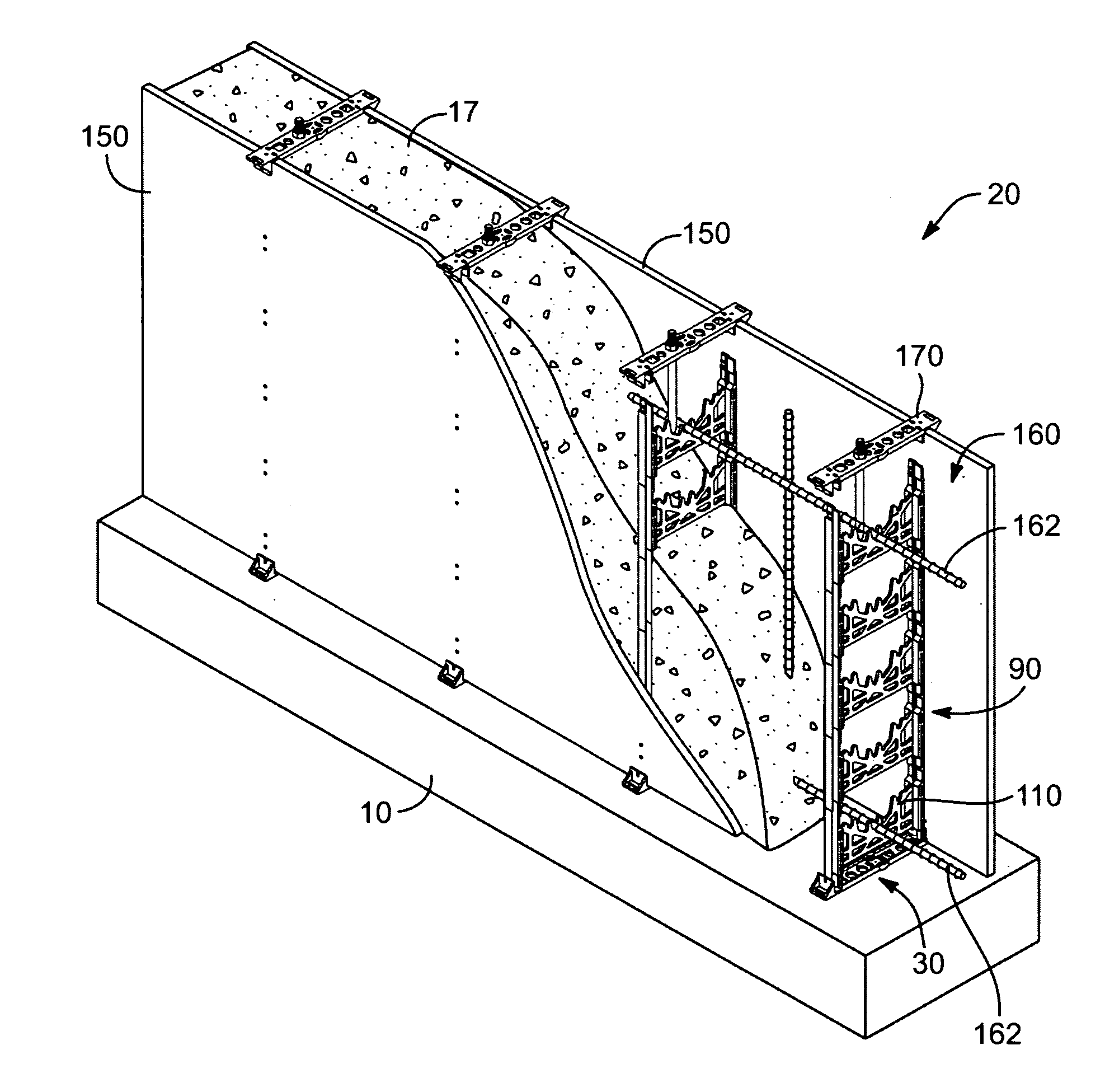
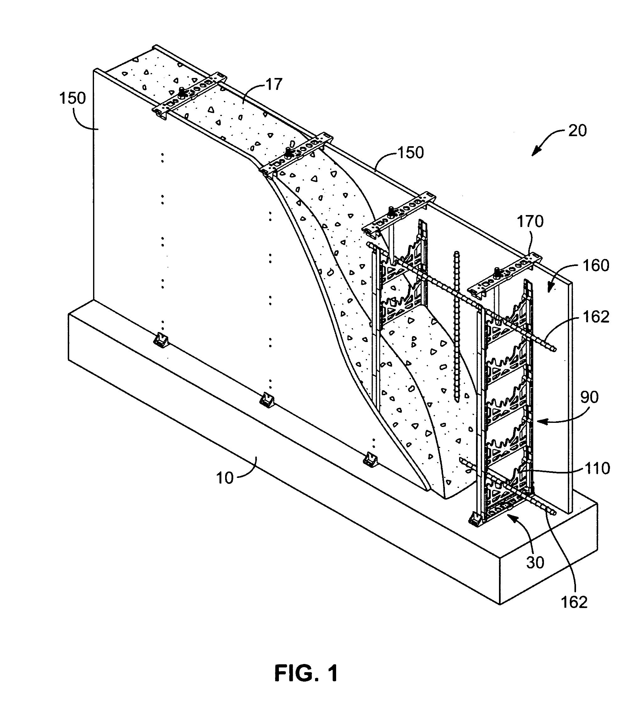
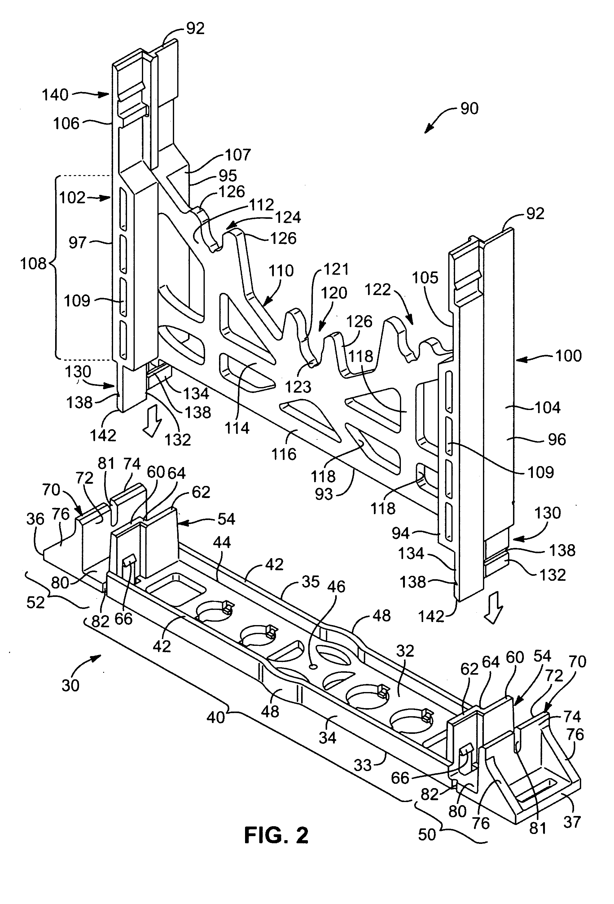
[0031]Referring first to FIG. 1, there is disclosed a partial view of a tie system 20, according to the present invention. The primary components of the tie system 20 comprise a base tie 30 and a wall tie 90. As will be set forth herein, the base tie 30 and wall tie 90 are utilized as support structure in conjunction with panel structures 150, such as typical plywood or Form ply, to build concrete forms for forming concrete walls for various residential and commercial buildings.

[0032]Such a tie system 20 includes multiple base ties 30 and multiple wall ties 90. The base ties 30 are placed and secured, in a spaced apart arrangement, to a concrete footing 10. Each base tie 30 receives a stack of wall ties 90 configured to extend in a vertical arrangement to form a tie stack 160. Each of the wall ties 90, within a stack, are configured to be directly interconnected together and configured to extend vertically, one above another. After running a first course of wall ties 90, horizontal ...


PUM


Abstract

A tie system and method for forming a wall from a hardenable pourable building material. In one embodiment, the tie system includes multiple ties configured to be directly interconnected into a vertically extending tie stack such that multiple tie stacks can be positioned over a footing in a spaced apart arrangement. The multiple tie stacks are configured to extend substantially perpendicular between substantially parallel panel structures. Each tie stack includes a base tie and one or more wall ties, each of which directly attach to each other in a vertically stacked arrangement.

Description

TECHNICAL FIELD[0001]The present invention relates generally to wall forming systems. More specifically, the present invention relates to a tie system for forming foundation walls and the like.BACKGROUND[0002]Many residential and light commercial structures are built on concrete foundation walls which are formed by pouring concrete into a system of forms that have been erected on a previously poured concrete footing. After the concrete has cured sufficiently, the forms are stripped from the concrete and in most cases soil is back filled on the exterior side of the concrete wall. Typically, the base of each foundation wall is supported on a concrete footing, which is wider than the thickness of the wall itself. Ideally, the centerline of the wall is aligned with the centerline of the footing. The footing spreads the load of the structure over a greater area and prevents uneven loading of the foundation wall.[0003]As set forth, once the footing is in place and hardened, a system of fo...

Claims


Application Information

Patent Timeline
IPC IPC(8): E04B1/16
CPCE04G11/085E04G17/064E04G17/14E04G17/12E04G17/0758
Inventor MCDONAGH, GREG
Owner PALADIN INDAL
Features
  • Generate Ideas
  • Intellectual Property
  • Life Sciences
  • Materials
  • Tech Scout
  • Unparalleled Data Quality
  • Higher Quality Content
  • 60% Fewer Hallucinations
Learn More