LED Light Fixture

a technology of led light fixtures and led drivers, which is applied in the field of street and roadway light fixtures, can solve the problems of high cost due to high complexity, difficult to keep electronic led drivers in water/air tight locations, and difficult to meet the requirements of high-luminance light fixtures using led modules as light sources for roadways and similar applications

Active Publication Date: 2009-10-08
IDEAL IND LIGHTING LLC
View PDF12 Cites 166 Cited by
  • Summary
  • Abstract
  • Description
  • Claims
  • Application Information

AI Technical Summary

Benefits of technology

[0019]The first end-portion at the first end of the extrusion has a lower surface and an extrusion-adjacent end surface. In highly preferred embodiments of the inventive LED light fixture, the extrusion-adjacent end surface and the lower surface form a first recess extending away from the first end of the extrusion and defining a first venting gap. The end surface along the first recess is preferably tapered such that the first venting gap is upwardly narrowed, thereby to direct and accelerate the air flow along the heat-dissipating surfaces.
[0020

Problems solved by technology

High-luminance light fixtures using LED modules as light source for roadway and similar applications present particularly challenging problems.
High costs due to high complexity becomes a particularly difficult problem when high luminance, reliability, and durability are essential to product success.
Keeping electronic LED drivers in a water/air-tight location may also be problematic, particularly when, as with roadway lights and the like, the light fixtures are constantly exposed to the elements and many LED modules are used.
Yet another cost-related challenge is the problem of achieving a high level of adaptability in order t

Method used


Image

  • LED Light Fixture
  • LED Light Fixture
  • LED Light Fixture

Examples


Embodiment Construction

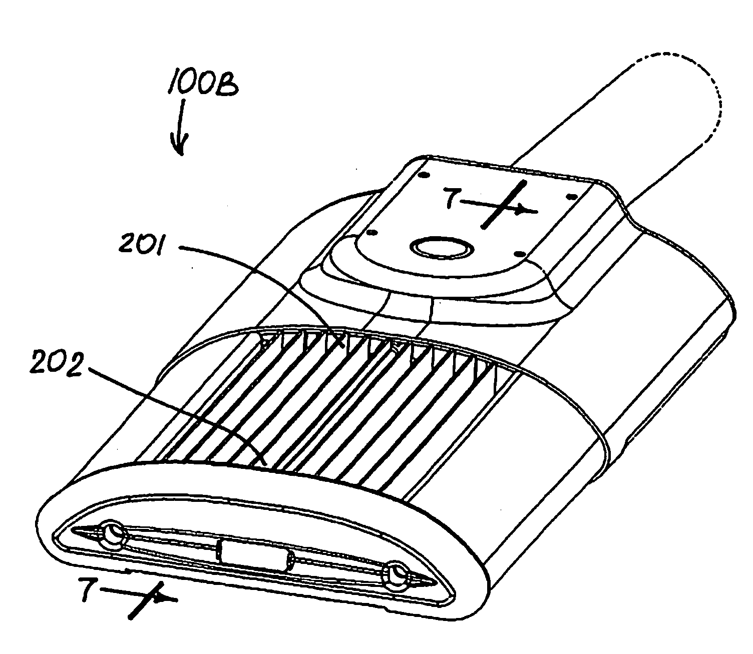
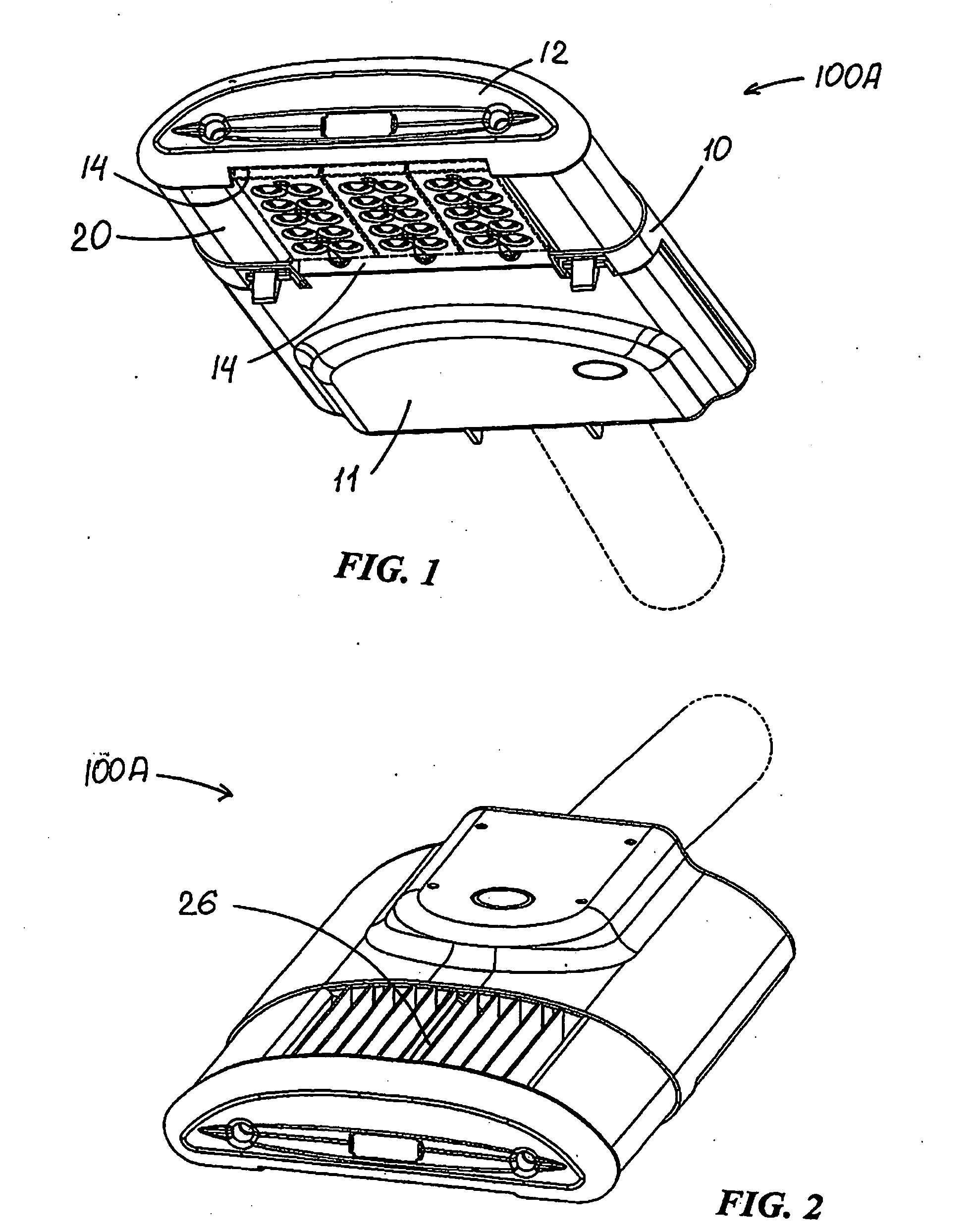
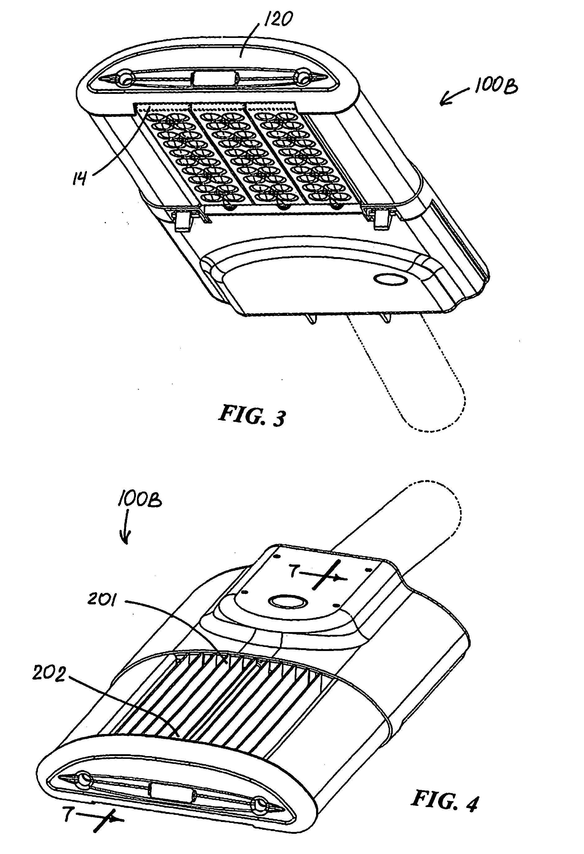
[0075]FIGS. 1-41 illustrate preferred embodiments of the LED light fixture 100A-100E in accordance with this invention. Common or similar parts are given same numbers in the drawings of all embodiments, and the floodlight fixtures are often referred to by the numeral 100, without the A or E lettering used in the drawings, and in the singular for convenience.

[0076]Floodlight fixture 100 includes a housing 10 that has a first end-portion 11 and a second end-portion 12 and a single-piece extrusion 20 that has first and second ends 201 and 202, respectively, with first and second end-portions 11 and 12 secured with respect to first and second ends 201 and 202, respectively. Single-piece extrusion 20 includes a substantially planar base 22 extending between first and second ends 201 and 202. Base 22 has an LED-adjacent surface 220 and an opposite surface 221. Single-piece extrusion 20 further has a heat-dissipating section 24 having heat-dissipating surfaces 241 extending from opposite s...


PUM


Abstract

An LED floodlight fixture includes (1) a housing that has (a) at least one end-portion and (b) a single-piece extrusion including (i) a base having an LED-adjacent surface and an opposite surface and (ii) a heat-dissipating section having heat-dissipating surfaces extending from the opposite surface, and (2) an LED arrangement mounted to the LED-adjacent surface in non-water/air-tight condition with respect to the housing. The housing preferably forms at least one venting gap to provide cool-air ingress to and along the heat-dissipating surfaces by upward flow of heated air therefrom. Additionally and/or alternatively, the base of the single-piece extrusion has one or more venting apertures to provide cool-air ingress for such purpose. One aspect of the invention involves the heat-dissipating section of the extrusion including a closed extruded wireway therealong enclosing wires extending to/from electrical component(s).

Description

RELATED APPLICATION[0001]This application is based in part on U.S. Provisional Application Ser. No. 61 / 042,690, filed Apr. 4, 2008, the entirety of the contents of which are incorporated herein by reference.FIELD OF THE INVENTION[0002]This invention relates to light fixtures and, more particularly, to street and roadway light fixtures and the like, including light fixtures for illumination of large areas. More particularly, this invention relates to such light fixtures which utilize LEDs as light source.BACKGROUND OF THE INVENTION[0003]In recent years, the use of light-emitting diodes (LEDs) for various common lighting purposes has increased, and this trend has accelerated as advances have been made in LEDs and in LED-array bearing devices, often referred to as “LED modules.” Indeed, lighting applications which have been served by fixtures using high-intensity discharge (HID) lamps and other light sources are now increasingly beginning to be served by LED modules. Such lighting appl...

Claims


Application Information

Patent Timeline
IPC IPC(8): F21V29/00F21S4/00
CPCF21S2/005F21V29/83F21V15/015F21V17/107F21V19/0055F21V23/002F21V29/004F21V31/03F21W2131/103F21Y2101/02F21Y2105/001F21V19/045F21K9/00F21V15/011F21S8/086F21V29/507F21V29/74F21V29/75F21V29/763F21V15/013F21Y2101/00F21Y2105/10F21Y2105/12F21V19/04F21K9/20F21Y2115/10F21V29/00F21V31/00F21V15/01F21V23/009F21W2131/40F21V29/503
Inventor KINNUNE, BRIANRUUD, ALAN J.GUILLIEN, WAYNEMILETICH, DONWILCOX, KURTSCHULTZ, RUSSELL S.
Owner IDEAL IND LIGHTING LLC
Why Eureka
Try Eureka