AI technical title is built by Patsnap AI team. It summarizes the technical point description of the patent document.
a technology of led light fixtures and led lamps, applied in the field of led light fixtures, can solve the problems of heat dissipation, difficult to solve fixture development problems, and the goals of heat dissipation and protection of electronic led drivers can often be conflicting
Active Publication Date: 2014-06-05
IDEAL IND LIGHTING LLC
View PDF6 Cites 5 Cited by
Summary
Abstract
Description
Claims
Application Information
AI Technical Summary
This helps you quickly interpret patents by identifying the three key elements:
Problems solved by technology
Method used
Benefits of technology
Benefits of technology
[0010]Another object of the invention is to provide an improved LED floodlight fixture that is readily adaptable for a variety of mounting positions and situations. Another object of the invention is to provide an improved LED floodlight that reduces development and manufacturing costs for LED floodlight for different floodlight applications.
[0011]Another object of the invention is to provide an improved LED floodlight with aerodynamic properties subjecting it to less wind load when mounted on a pole or similar mounting.
[0023]In certain preferred embodiments the frame structure preferably includes a vent permitting air flow to and from the LED assembly. Such venting facilitates cooling the LED assembly.
Problems solved by technology
Floodlights using LED modules as light source for various applications present particularly challenging problems in fixture development, particularly when floodlight mounting locations and structures will vary.
Heat dissipation is another problem for LED floodlights.
And, the goals of dealing with heat dissipation and protection of electronic LED drivers can often be conflicting, contrary goals.
Wind load is another problem for LED floodlights and floodlights that are mounted on poles in general.
Some LED floodlights of the prior art are bulky in size.
Given their bulky nature these floodlights are very susceptible to wind load damage.
Method used
Image
Click on the blue label to locate the original text in one second.
Reading with bidirectional positioning of images and text.
Examples
Embodiment Construction
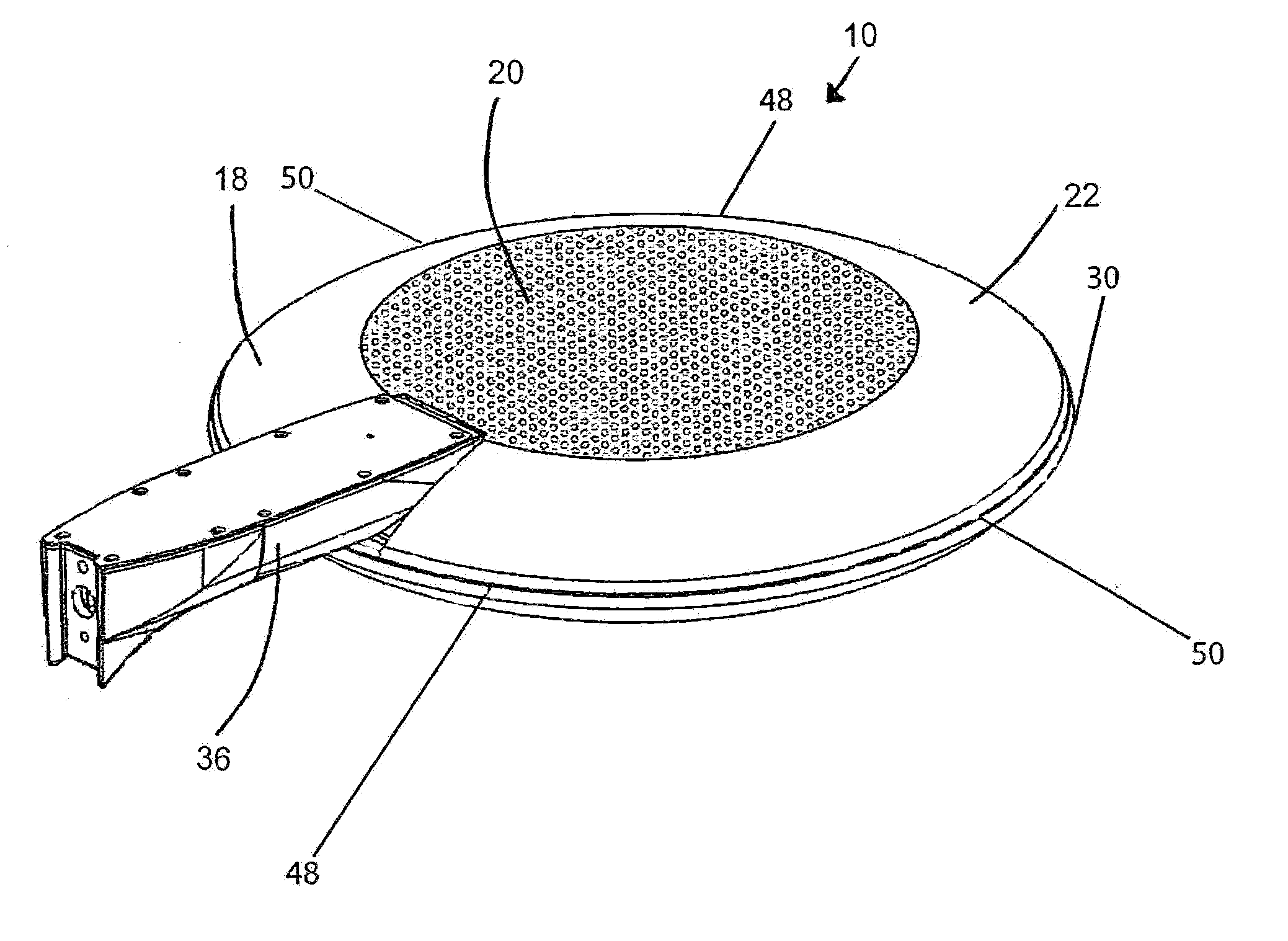
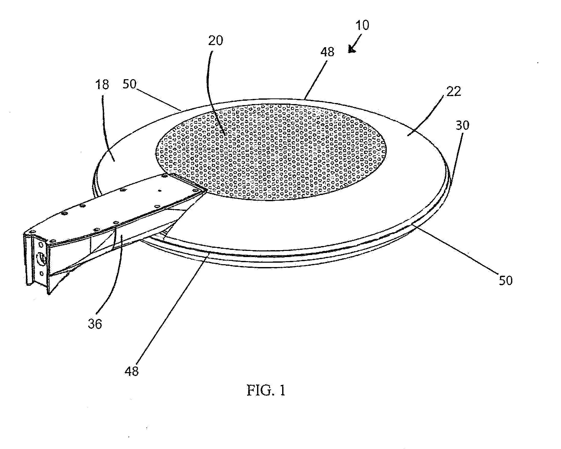
[0054]FIGS. 1-4 illustrate a preferred LED floodlight fixture in accordance with this invention. LED floodlight fixture 10 includes two major principal axes (illustrated in FIGS. 5-7 as 1, 2) in a fixture plane 42 (illustrated in FIG. 1). The dimensions parallel to its third principal axis (illustrated in FIGS. 7 and 8 as 3) are substantially smaller than the largest dimensions parallel to fixture plane 42. A simple graphical explanation of the three principal axes (1-3) is shown in FIGS. 5-7.
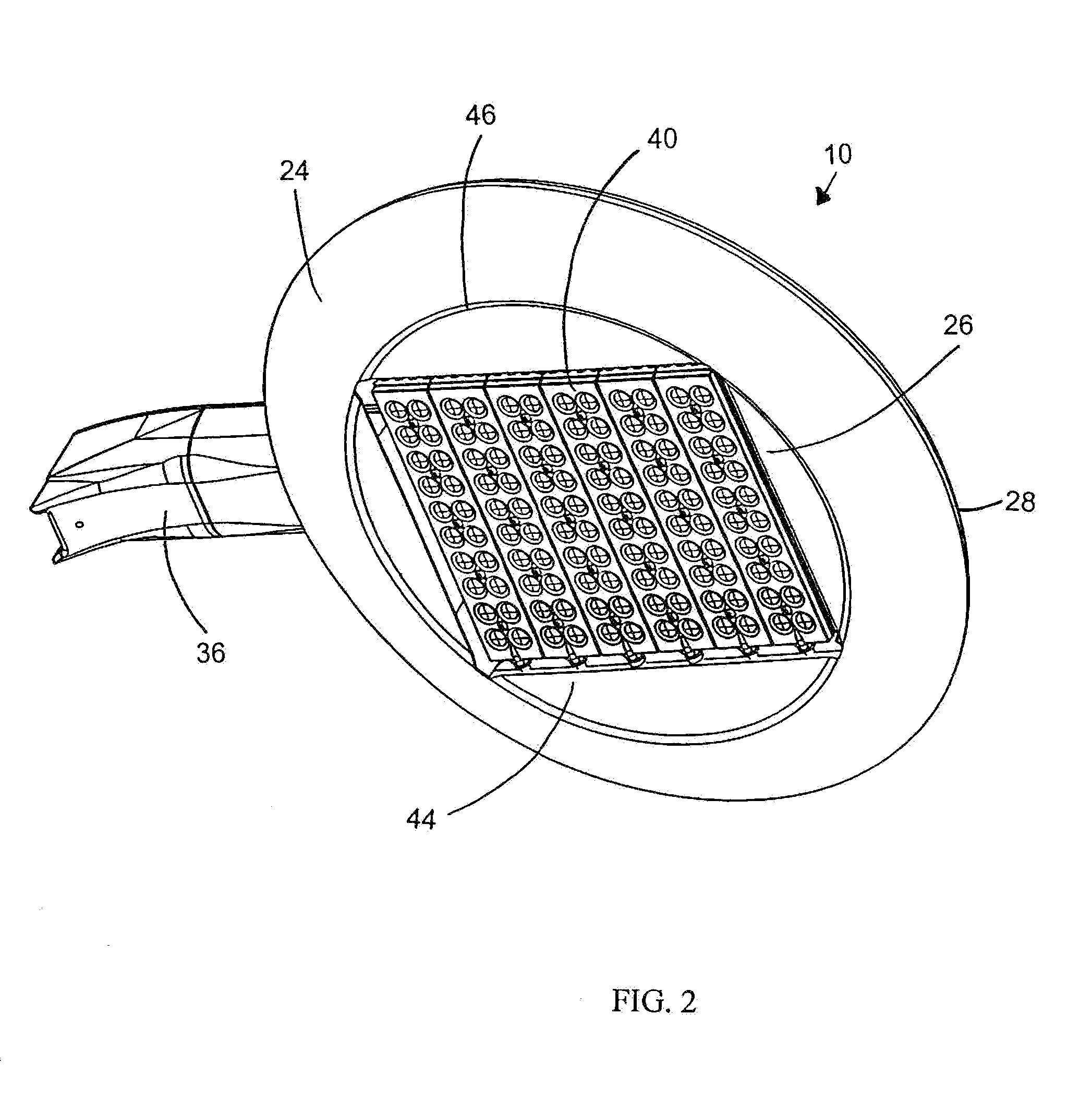
[0055]As best seen in FIGS. 1-3, fixture 10 is characterized by a first outer surface 18 having a first central portion 20 and a first edge-adjacent portion 22, an opposite second outer surface 24 having a second central portion 44 substantially aligned with first central portion 20 and encompassing a light-emitting region 26 and a second edge-adjacent portion 28 having a boundary 46. Second central portion 44 also includes second edge-adjacent portion 28 having a boundary 46 with second centra...
PUM
Abstract
An LED light fixture having a light-emitting region and a perimetrical structure therearound. The light-emitting region includes at least one LED-array module supported by an LED heat sink open for air / water-flow. The perimetrical structure has first and second opposite substantially-aligned edge-adjacent portions each extending along the light-emitting region and meeting each other at a perimetrical edge. The first and second edge-adjacent portions converge toward each other at positions progressively closer to the perimetrical edge to form aerodynamic-drag-reducing cross-sectional profiles transverse to the fixture plane and extending in substantially all fixture-plane directions from the intersection of its two major principal axes.
Description
RELATED APPLICATION[0001]This application is a continuation of patent application Ser. No. 11 / 864,298, filed Sep. 28, 2007. This application is also a continuation-in-part of patent application Ser. No. 13 / 834,525, filed Mar. 15, 2013, which is a continuation of patent application Ser. No. 13 / 294,459, filed Nov. 11, 2011, now U.S. Pat. No. 8,425,071, issued Apr. 23, 2013, which is a continuation of patent application Ser. No. 12 / 629,986, filed Dec. 3, 2009, now U.S. Pat. No. 8,070,306, issued Dec. 6, 2011, which is a continuation of patent application Ser. No. 11 / 860,887, filed Sep. 25, 2007, now U.S. Pat. No. 7,686,469, issued Mar. 30, 2010, which is a continuation-in-part of now abandoned patent application Ser. No. 11 / 541,908, filed Sep. 30, 2006. The entire contents of each of the parent applications are incorporated herein by reference.FIELD OF THE INVENTION[0002]This invention relates to lighting fixtures and, more particularly, to light fixtures using LED modules.BACKGROUND O...
Claims
Application Information
Patent Timeline
Application Date:The date an application was filed.
Publication Date:The date a patent or application was officially published.
First Publication Date:The earliest publication date of a patent with the same application number.
Issue Date:Publication date of the patent grant document.
PCT Entry Date:The Entry date of PCT National Phase.
Estimated Expiry Date:The statutory expiry date of a patent right according to the Patent Law, and it is the longest term of protection that the patent right can achieve without the termination of the patent right due to other reasons(Term extension factor has been taken into account ).
Invalid Date:Actual expiry date is based on effective date or publication date of legal transaction data of invalid patent.
Patent Type & AuthorityApplications(United States)

