Parallel mechanism

Inactive Publication Date: 2009-10-15
MURATA MASCH LTD
View PDF7 Cites 38 Cited by
  • Summary
  • Abstract
  • Description
  • Claims
  • Application Information

AI Technical Summary

Benefits of technology

[0021]Thus, when any of the ball joints comes loose, the driving of the actuator is stopped. The parallel mechani

Problems solved by technology

On the other hand, when the ball joint comes loose, that is, when the ball-shaped head of the ball

Method used


Image

  • Parallel mechanism
  • Parallel mechanism
  • Parallel mechanism

Examples


Example

[0029]Preferred embodiments of the present invention will be described below in detail with reference to the drawings. In the drawings, the same elements are denoted by the same reference numerals, and duplicate descriptions are omitted.

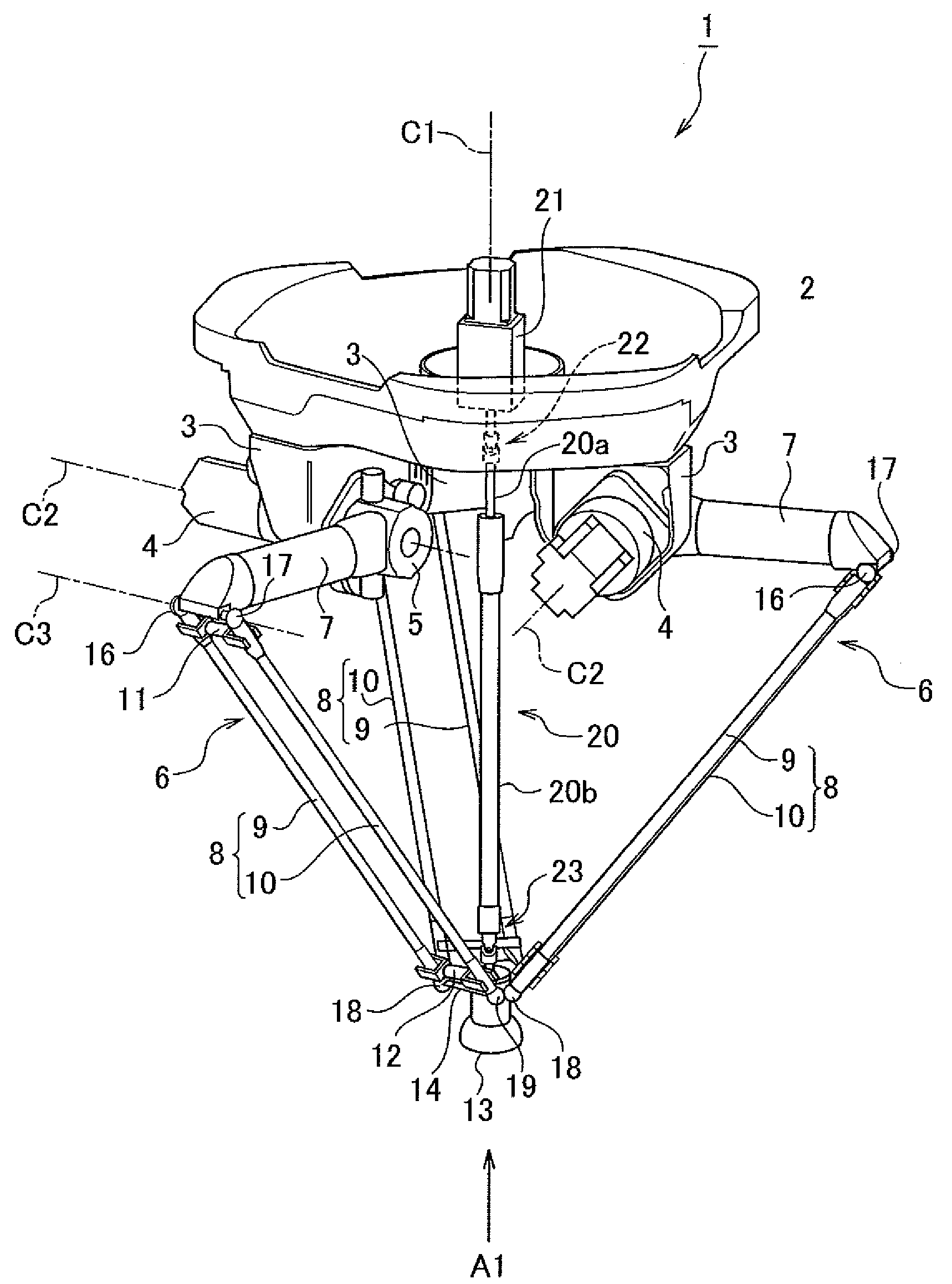
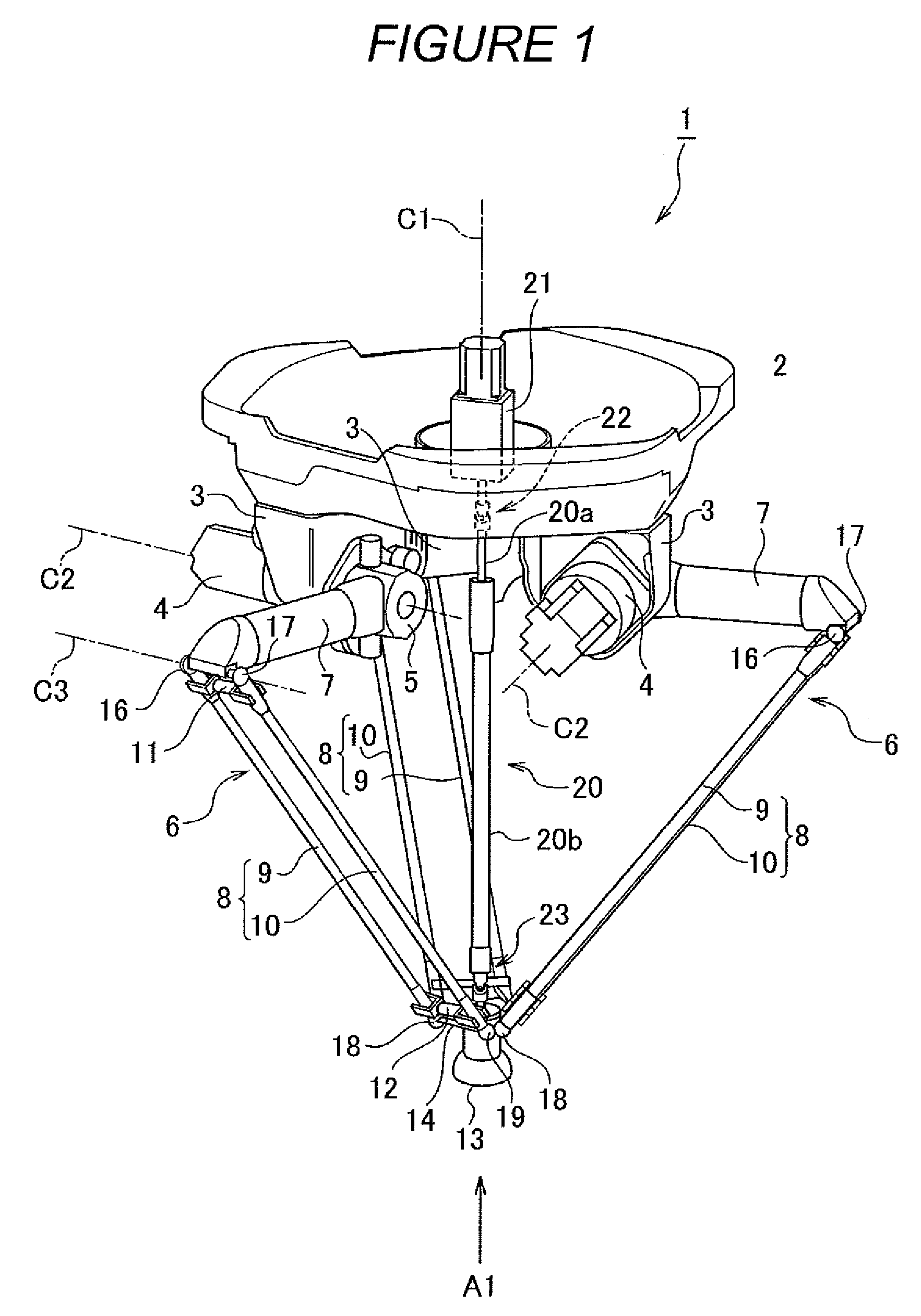
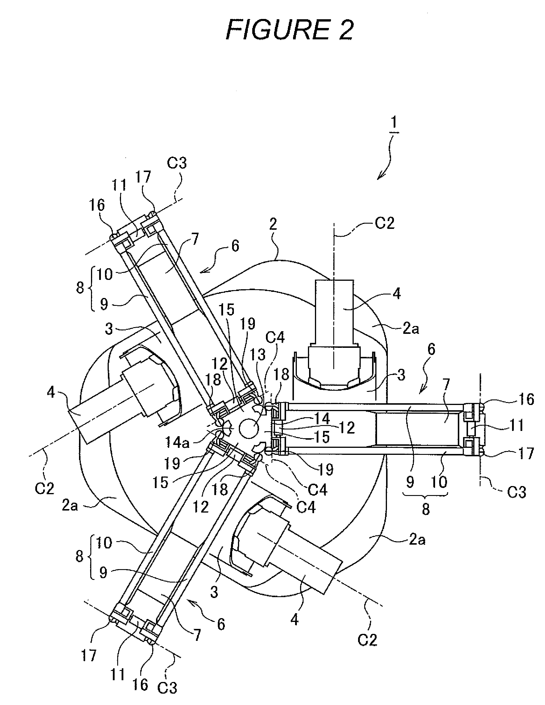
[0030]First, the general configuration of a parallel mechanism according to a preferred embodiment will be described with reference to FIGS. 1 and 2. FIG. 1 is a perspective view showing the general configuration of the parallel mechanism 1 according to a preferred embodiment of the present invention. FIG. 2 is a diagram showing the parallel mechanism 1 as viewed from the direction of arrow A1 in FIG. 1.

[0031]The parallel mechanism 1 has a base portion at the top thereof. The parallel mechanism 1 is supported by fixing a flat mounting surface 2a of the base portion 2 arranged on the bottom surface side thereof, to, for example, a flat ceiling. On the other hand, three support members 3 are provided on the bottom surface side of the base portion 2. An...


PUM


Abstract

A parallel mechanism includes a base, actuators attached to the base, a plurality of arms coupled together in parallel, and a sensing device. Each of the arms has a first link, one end of which is coupled to the actuator, a second link through which the other end of the first link and a bracket are coupled together, a ball joint through which one end of the second link and the other end of the first link are swingably coupled together, and a ball joint through which the other end of the second link and the bracket are swingably coupled together. Each of the ball joints includes a ball stud including a ball-shaped head, a socket swingably holding the ball-shaped head of the ball stud, and a conductive member interposed between the ball-shaped head and the socket. The sensing device senses when at least one of the plurality of ball joints is loose, based on whether or not the ball stud and the socket are electrically continuous with one another.

Description

CROSS-REFERENCE TO RELATED APPLICATIONS[0001]This application claims priority under 35 U.S.C. 119 to Japanese Patent Application No. 2008-102969, filed on Apr. 10, 2008, which application is hereby incorporated by reference in its entirety.BACKGROUND OF THE INVENTION[0002]1. Field of the Invention[0003]The present invention relates to a parallel mechanism, and in particular, to a parallel mechanism including a pair of arms coupled together through a ball joint.[0004]2. Description of Related Art[0005]A parallel mechanism in which a base portion that includes a support base and a bracket with an end effector attached thereto are coupled together in parallel through a plurality of arms is known. That is, in the parallel mechanism, electric motors are arranged in parallel. Furthermore, a plurality of arms coupled to the respective motors ultimately operate one bracket.[0006]In each arm, a ball and a socket provided in a ball joint are held by the tensile force of a spring. However, one...

Claims


Application Information

Patent Timeline
IPC IPC(8): B25J18/00B25J19/02B25J19/06
CPCB25J13/087B25J17/0266B25J17/0283Y10T74/20305B25J9/0051Y10T74/20341B25J19/06B23Q1/44B23Q1/70B25J11/00F16H21/46
Inventor NISHIDA, TATSUHIKONAKANISHI, HIDEAKINAKAO, TAKASHIYAMASHITA, MANABU
Owner MURATA MASCH LTD
Why Eureka
Try Eureka