Attachment, liquid container, and liquid supply apparatus

a technology for liquid supply apparatus and liquid containers, which is applied in printing and other directions, can solve the problems of increasing the length of each ink supply tube, increasing the amount of ink consumed by the apparatus, and increasing the pressure variation of the ink supply tube, so as to achieve easy and quick mounting

Inactive Publication Date: 2009-10-15
SEIKO EPSON CORP
View PDF12 Cites 5 Cited by
  • Summary
  • Abstract
  • Description
  • Claims
  • Application Information

AI Technical Summary

Benefits of technology

[0018]Accordingly, it is an objective of the present invention to provide low-cost and easy-to-use attachment and liquid supply apparatus that are easily and quickly mounted on a liquid ejection apparatus.
[0019]It is another objective of the present invention to provide a liquid container and a liquid supply apparatus that are compatible with a liquid pressurization supply system through an air pressurizing portion of a liquid ejection apparatus and stabilize supply of liquid.

Problems solved by technology

However, since the scanning distance of the carriage is relatively great in this apparatus, the length of each ink supply tube is increased and thus pressure variation occurs in the ink supply tube.
Further, since the recording head includes the increased number of the nozzles, as has been described, the apparatus consumes an increased amount of ink.
The amount of the ink supplied to the sub tank thus may become insufficient.
A large-sized cartridge is thus actually unusable.
Thus, the greater the work load of the printer becomes, the more often the cartridge must be replaced.
This complicates operation of the printer and raises the running cost of the printer.
Particularly, if the printer is a small-sized type or a thin type and the space for accommodating the cartridge holder is restricted, the amount of the ink retained in the cartridge becomes correspondingly small.
In this case, the above-described problem is pronounced.
However, there may be a case in which the external tank for feeding the ink Ik is not compatible with a pressurization supply system of the ink Ik through the pressurization pump 20 of the printer 301.
In this case, the printer 301 may cause an error in operation.
This prolongs the time needed for accomplishing the procedure for mounting the attachment.
The cost for providing the attachment thus increases.
That is, the attachment of Japanese Laid-Open Patent Publication No. 2003-326732 complicates the procedure for mounting the attachment on the cartridge holder as a replacement of the cartridge and increases the cost.
In this regard, the attachment is not necessarily easy to employ.

Method used


Image

  • Attachment, liquid container, and liquid supply apparatus
  • Attachment, liquid container, and liquid supply apparatus
  • Attachment, liquid container, and liquid supply apparatus

Examples


first embodiment

[0051]the present invention will now be described with reference to FIGS. 1 to 6.

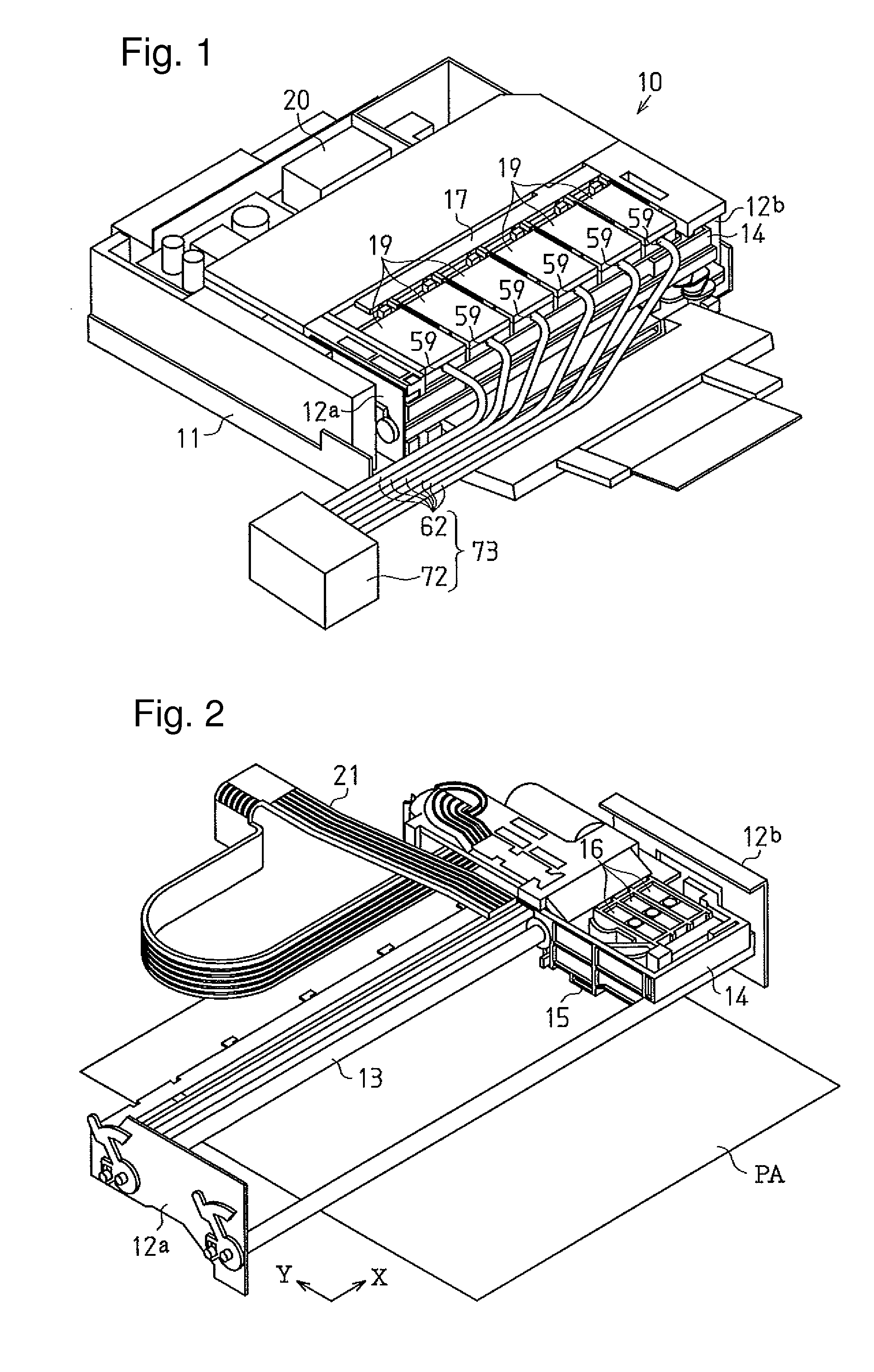
[0052]As shown in FIGS. 1 and 2, an inkjet printer (hereinafter, a “printer”) 10, or a liquid ejection apparatus of the first embodiment, includes a substantially box-like body casing 11. A pair of opposing frame members 12a, 12b are provided at opposing lateral sides of the body casing 11. A rod-like guide shaft 13 extends between the frame members 12a, 12b. A carriage 14 is movably passed through the guide shaft 13. The carriage 14 is thus reciprocated in a direction (a main scanning direction X of FIG. 2) along the longitudinal direction of the guide shaft 13 while driven by the drive force generated by a non-illustrated carriage motor provided in the printer 10.

[0053]A recording head 15 is formed on a bottom surface of the carriage 14 as a liquid ejection head. A plurality of nozzles (not shown) are defined in the recording head 15 for ejecting ink as liquid. Valve units 16 are arranged on an upper ...


PUM


Abstract

An attachment is mounted on a cartridge holder of a printer as a replacement of an ink cartridge. An ink outlet member having a link passage is separably secured to an attachment body. Ink is supplied from the exterior to the ink outlet member through an ink supply tube. When the attachment is mounted on the cartridge holder, a downstream end of the ink outlet member is positioned with respect to and connected to an ink supply needle of the printer. Accordingly, the attachment is easily and quickly installed in a liquid ejection apparatus. This reduces costs and makes it easy to use the attachment.

Description

CROSS-REFERENCE TO RELATED APPLICATIONS[0001]This application is based upon and claims the benefit of priority from prior Japanese Patent Applications No. 2005-025985, filed on Feb. 2, 2005, No. 2.005-025986, filed also on Feb. 2, 2005, and No. 2005-042589, filed on Feb. 18, 2005, the entire contents of which are incorporated herein by reference.BACKGROUND OF THE INVENTION[0002]The present invention relates to attachments and liquid supply apparatuses that are preferably used in liquid ejection apparatuses. The present invention also relates to liquid containers and liquid supply apparatuses, and, more particularly, to liquid containers and liquid supply apparatuses that replace liquid cartridges in a liquid ejection apparatus, such as an inkjet recording apparatus, and allow supply of a liquid, such as ink, from an external source.[0003]For example, an inkjet recording apparatus (a liquid ejection apparatus) typically includes an inkjet recording head (a liquid ejecting portion) an...

Claims


Application Information

Patent Timeline
Patent Type & Authority Applications(United States)
IPC IPC(8): B41J2/175
CPCB41J2/175B41J2/1752B41J2/17556B41J2/17553B41J2002/17516B41J2/17523B41J2/17503B41J2/17
Inventor KOBAYASHI, ATSUSHIKIMURA, HITOTOSHI
Owner SEIKO EPSON CORP
Why Eureka
Try Eureka