Apparatus and method for identifying disk drives with unreported data corruption

a technology of unreported data and apparatus, applied in the field of raid controllers, can solve the problems of not all raid levels provide data redundancy, require fairly complex controller and parity generation circuitry or software, and require a large amount of hardware and softwar

Inactive Publication Date: 2009-10-15
DOT HILL SYST
View PDF18 Cites 121 Cited by
  • Summary
  • Abstract
  • Description
  • Claims
  • Application Information

AI Technical Summary

Benefits of technology

[0020]Other features and advantages of the present invention will become ...

Problems solved by technology

Not all RAID levels provide data redundancy, however.
For example, a RAID 0 array uses a striping technique to store data stripe-wise across multiple storage devices, but does not provide a copy of the data stored elsewhere on storage devices of the array that can be used to reconstruct data if a storage device fails.
Although such arrangements provide for fault tolerance, and can provide somewhat improved I/O performance, they all require at least three storage devices to implement, and require fairly complex controller and parity generation circuitry or software.
Although redundant RAID arrays protect against single storage device failures quite well, there are other classes of problems where storage devices do not detect and report an error, but instead return data that is different from the data that was previously written to the storage device at the location now being read.
Occasionally, a storage device will fail in such a manner that it is una...

Method used


Image

  • Apparatus and method for identifying disk drives with unreported data corruption
  • Apparatus and method for identifying disk drives with unreported data corruption
  • Apparatus and method for identifying disk drives with unreported data corruption

Examples


second embodiment

[0114]Referring now to FIG. 11, a flowchart illustrating an analyze operation for a RAID array following a stripe coherency error is shown. Flow begins at block 1104.

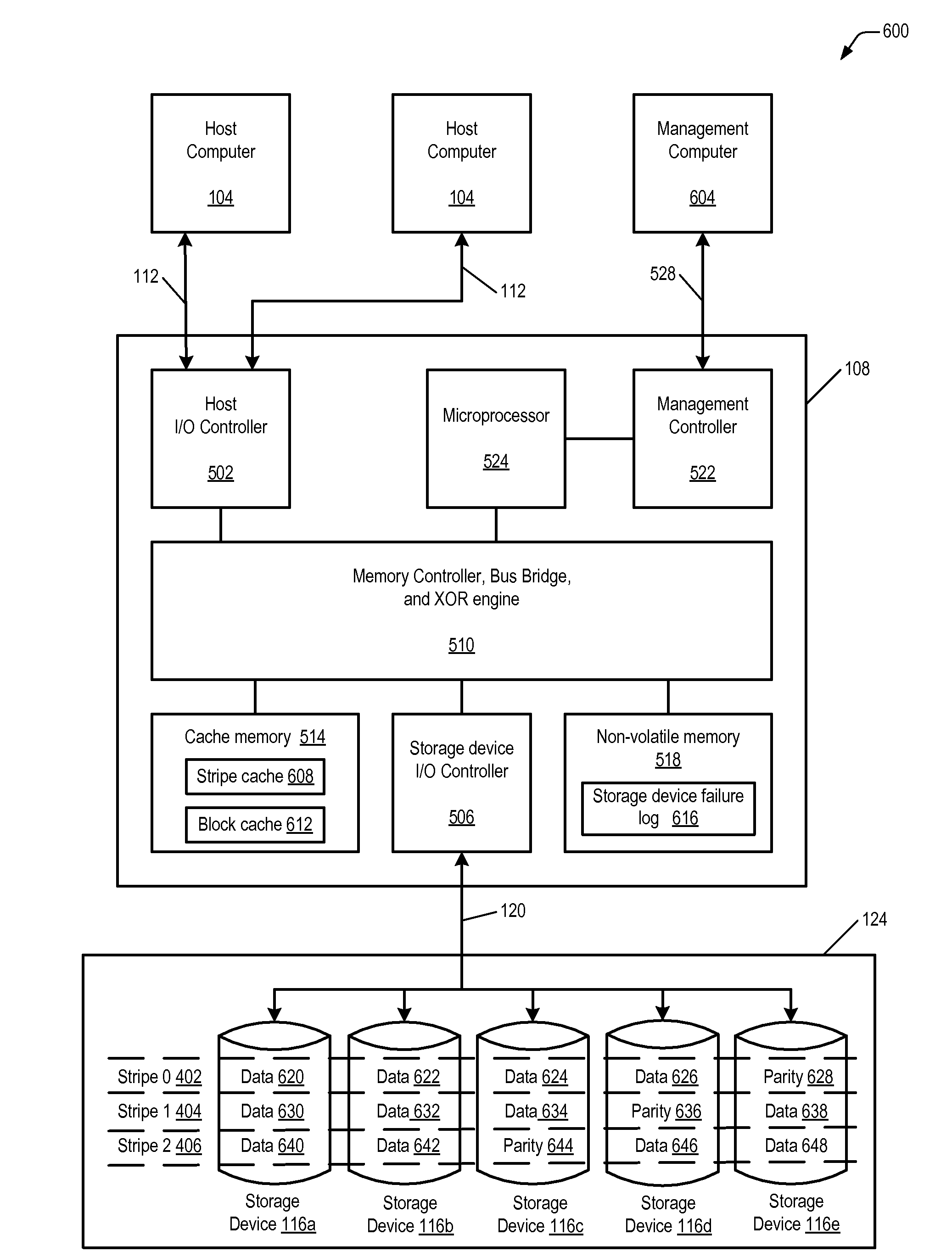
[0115]At block 1104, writes are blocked to the current stripe by locking the current stripe in stripe cache 608, i.e., the RAID controller 108 prevents writes to the current stripe of the redundant array. Recall that data is previously read into the stripe cache 608 in blocks 704, 804, and 904 of FIGS. 7, 8, and 9, respectively. Additionally, subsequent times through the outer loop of FIG. 11, the data is read into the stripe cache 608 at block 1140, as described below. Flow proceeds to block 1108.

[0116]At block 1108, the RAID controller 108 allocates a new buffer in cache memory equal to the block size. This new buffer will be the block cache 612 of FIG. 6. The size of block cache will be the size of a block, which is the amount of data on one storage device 116 in one stripe 402-410. Flow proceeds to block 1112.

[0117]...

third embodiment

[0129]Referring now to FIG. 12, a flowchart illustrating an analyze operation for a RAID array following a stripe coherency error is shown. This embodiment is similar to that shown in FIG. 11, with the exception that this embodiment does not continue to analyze blocks on storage devices 116 that have previously been identified and recorded as failing storage devices 116. Flow begins at block 1204.

[0130]At block 1204, writes are blocked to the current stripe by locking the current stripe in stripe cache 608, i.e., the RAID controller 108 prevents writes to the current stripe of the redundant array. Recall that data is previously read into the stripe cache 608 in blocks 704, 804, and 904 of FIGS. 7, 8, and 9, respectively. Additionally, subsequent times through the outer loop of FIG. 12, the data is read into the stripe cache 608 at block 1240, as described below. Flow proceeds to block 1208.

[0131]At block 1208, the RAID controller allocates a new buffer in cache memory 514 equal to t...


PUM


Abstract

A RAID controller uses a method to identify a storage device of a redundant array of storage devices that is returning corrupt data to the RAID controller. The method includes reading data from a location of each storage device in the redundant array a first time, and detecting that at least one storage device returned corrupt data. In response to detecting corrupt data, steps are performed for each storage device in the redundant array. The steps include reading data from the location of the storage device a second time without writing to the location in between the first and second reads, comparing the data read the first and second times, and identifying the storage device as a failing storage device if the compared data has a miscompare. Finally, the method includes updating the location of each storage device to a new location and repeating the steps for the new location.

Description

CROSS REFERENCE TO RELATED APPLICATION(S)[0001]This application claims the benefit of U.S. Provisional Application Ser. No. 61 / 044,966, filed Apr. 15, 2008, which is hereby incorporated by reference for all purposes.FIELD OF THE INVENTION[0002]The present invention relates in general to the field of RAID controllers and particularly to an apparatus and method for identifying defective storage devices when data corruption is not reported by the storage device.BACKGROUND OF THE INVENTION[0003]The need to store digital files, documents, pictures, images and other data continues to increase rapidly. In connection with the electronic storage of data, systems incorporating more than one storage device have been devised. In general, using a number of storage devices in a coordinated fashion in order to store data can increase the total storage volume of the system. In addition, data can be distributed across the multiple storage devices such that data will not be irretrievably lost if one ...

Claims


Application Information

Patent Timeline
IPC IPC(8): G06F11/20G06F12/00G06F11/14
CPCG06F11/1076G06F2211/1088G06F11/2094
Inventor SHELLHAMER, JEFFERY LAWRENCE
Owner DOT HILL SYST
Why Eureka
Try Eureka