
Restraint mitt

a technology of mitts and restraints, applied in the field of patent safety devices, can solve the problems of minority of restraint alternatives that fail severe injury to self, and inability to use mechanical restraints and restraints

Inactive Publication Date: 2009-10-22
DUPLESSIE RONALD F
View PDF44 Cites 13 Cited by
  • Summary
  • Abstract
  • Description
  • Claims
  • Application Information

AI Technical Summary

Benefits of technology

This invention relates to beds designed specifically for people who are unable to move around freely without falling down on their own. These beds have special features like ladders made up of metal strips attached at regular intervals along its edges. They allow them easy access while still being able to be moved about easily by themselves.

Problems solved by technology

The technical problem addressed in this patent text is the need for a better method of restraint for patients who have had strokes or other brain damage and are unable to move their arms and hands. Current methods of restraints can be uncomfortable and can cause harm to patients. The invention provides a solution that allows the arms to be mobile while preventing the hands from being able to grasp objects.

Method used


Image

  • Restraint mitt
  • Restraint mitt
  • Restraint mitt

Examples


Embodiment Construction

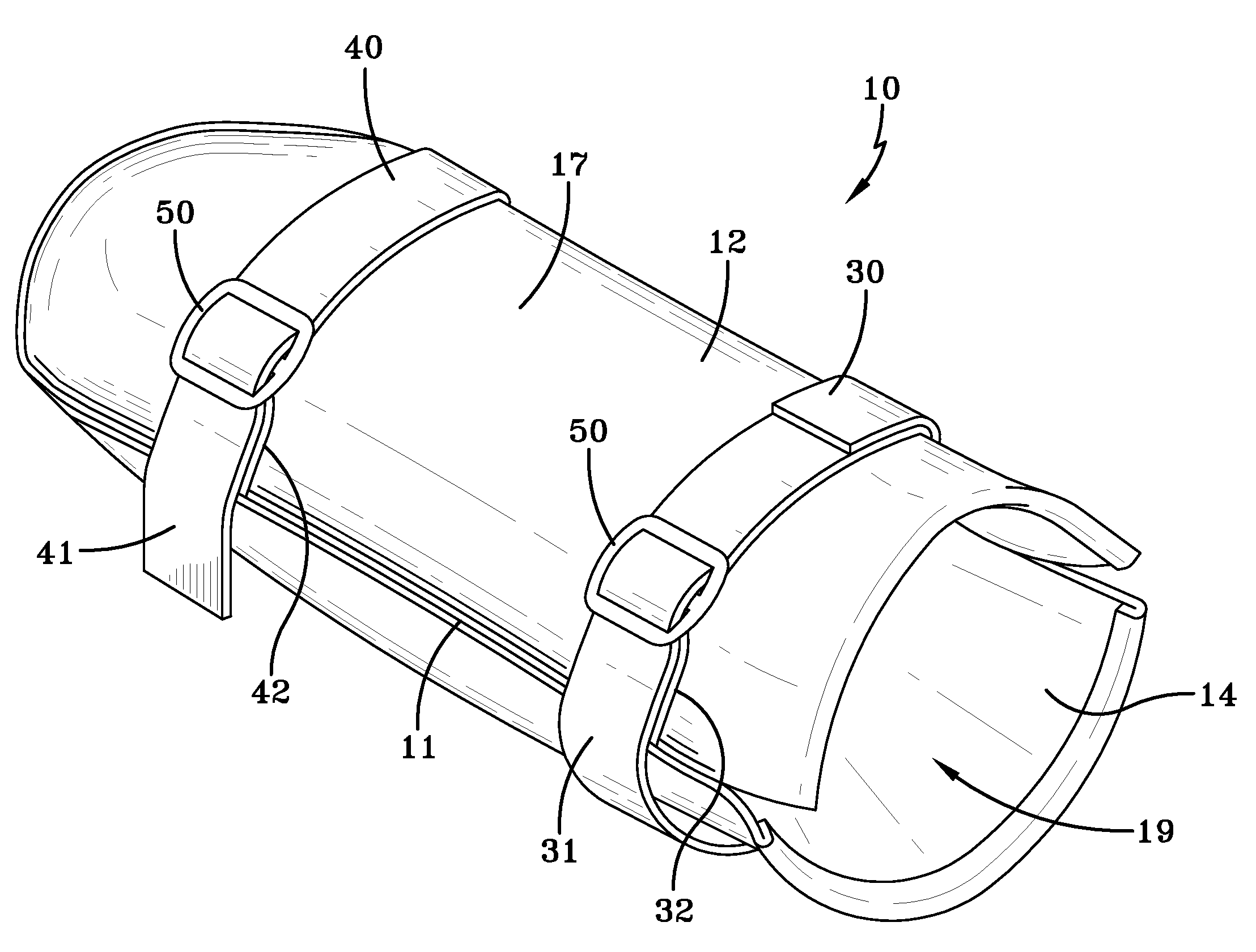
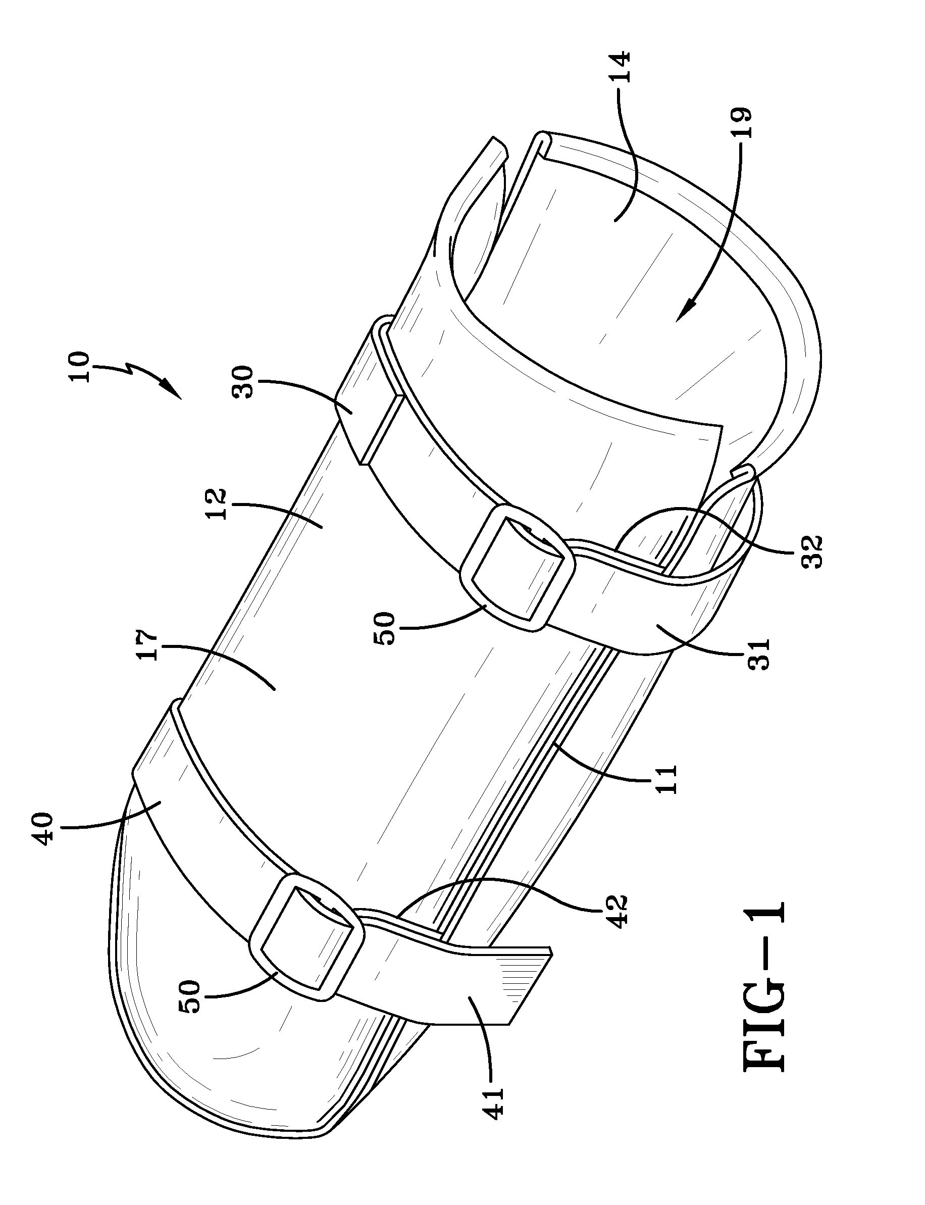
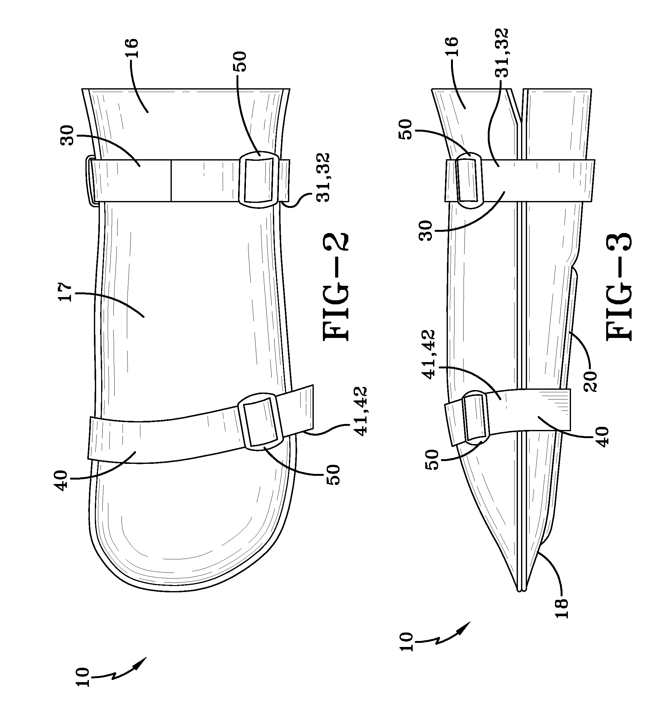
[0038]With reference to FIGS. 1-5, a perspective view of the thumbless mitt for receiving a hand is shown. As shown in FIGS. 3, 4 and 5, the thumbless mitt 10 has a cloth outer shell cover 12, a cloth inner liner 14 and a non-pliable palm center 20 interposed between the inner liner 14 and the outer shell cover 12 on a palm facing portion 18 of the mitt 10. As shown in FIGS. 8 and 8A, the cloth inner liner 14 defines an inner chamber 19 into which the entire hand 2 shown in dashed lines is inserted. The non-pliable palm center 20 extends from a palm location of the mitt 10 to an adjacent and along the fingers location of the mitt 10. Preferably, the palm center 20 is positioned centered on the palm side 18 of the mitt 10 and having a sufficient width to block at least two middle fingers from bending in a grasping position beyond the palm center 20.

[0039]Along the edges of the cloth outer shell cover 12 and the cloth inner liner 14 are seam edges 11. The seam edges 11 are preferably ...


PUM


Abstract

A thumbless mitt 10 for receiving a hand 2 has a cloth outer shell cover 12, a cloth inner liner 14 and a non-pliable palm center 20 interposed between the inner liner 14 and the outer shell cover 12 on a palm facing portion 18 of the mitt 10. The cloth inner liner 14 defines an inner chamber 19 into which the entire hand 2 is inserted. The non-pliable palm center 20 extends from the palm location to adjacent and along the fingers location, preferably centered on the palm side 18 of the mitt 10 and having a width sufficient to block at least two middle fingers from bending in a grasping position beyond the palm center 20. Two pairs of straps 30 and 40 are strategically located to prevent removal and or rotation of the hand 2inside the mitt 10.

Description


Claims


Application Information

Patent Timeline
Owner DUPLESSIE RONALD F
Learn More