
Method and Apparatus for Data Preview

a data preview and data technology, applied in the field of digital oscilloscopes, can solve the problems of slowing down the display of updated information, reprocessing a large amount of information,

Active Publication Date: 2009-10-29
TELEDYNE LECROY
View PDF7 Cites 12 Cited by
  • Summary
  • Abstract
  • Description
  • Claims
  • Application Information

AI Technical Summary

Benefits of technology

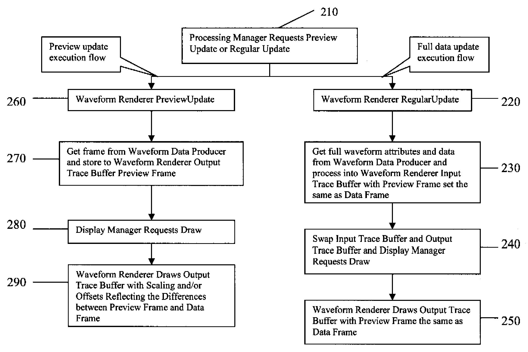
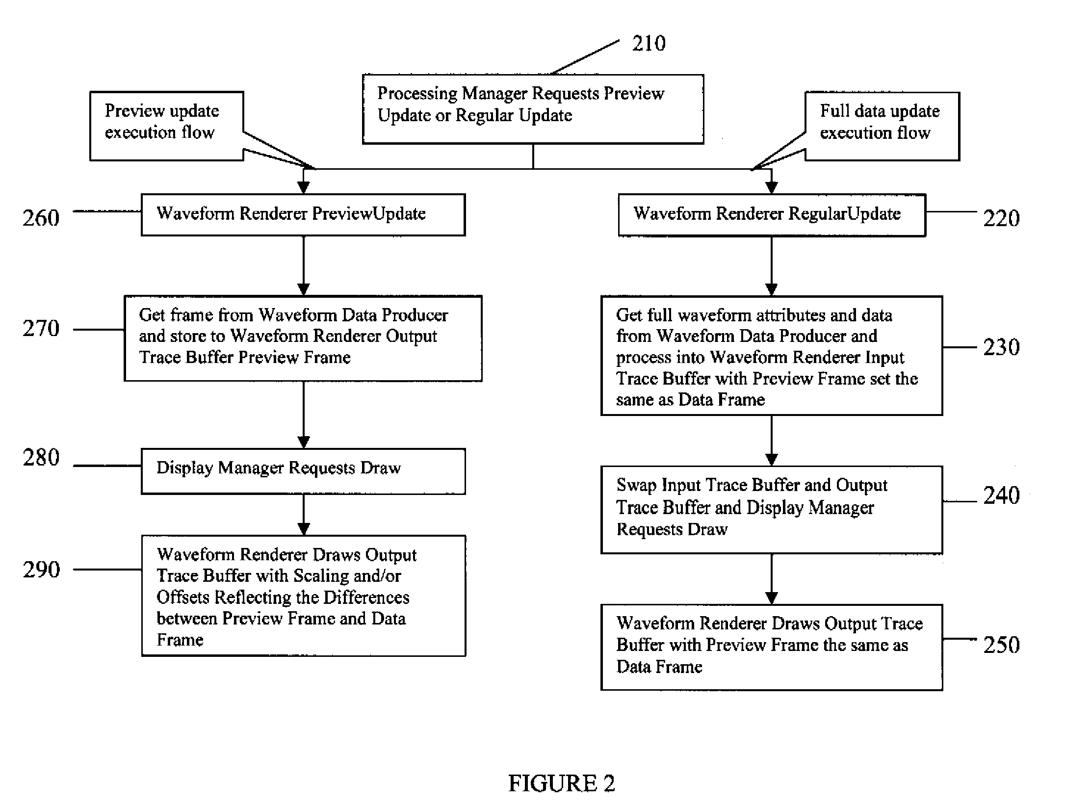
[0006]Furthermore, in accordance with the invention, by maintaining two waveform trace buffers, it is possible to perform the inventive preview update on the previous trace data concurrently with the “regular” processing of newly acquired incoming data, including any waveform trace update that depends on the full waveform data. This results in a responsive system where the preview waveform trace is displayed quickly in response to user changes to the scale, offset, or other settings that might result in an update of the displayed waveform data. The updated preview display is in turn eventually replaced by the fully accurate waveform trace when the “regular” update completes processing the next incoming acquired data, or waveform data otherwise stored, imported, generated from a simulation or any other source for waveform data.
[0008]This technique may be applied to any scenario wherein incoming data is being received and displayed, and where any settings might be changed, automatically, or by a user, that would normally result in a reprocessing of a large amount of information, thus slowing down the display of that updated information.

Problems solved by technology

This technique may be applied to any scenario wherein incoming data is being received and displayed, and where any settings might be changed, automatically, or by a user, that would normally result in a reprocessing of a large amount of information, thus slowing down the display of that updated information.

Method used


Image

  • Method and Apparatus for Data Preview
  • Method and Apparatus for Data Preview
  • Method and Apparatus for Data Preview

Examples


Embodiment Construction

[0015]The invention will now be described making reference to the drawings. Within a digital oscilloscope there may be a number of different types of waveform traces. The present invention may be applied to most, if not all, of them, with slight implementation variations depending on the specifics of the waveform type. Therefore, the processing in accordance with the invention is not limited to any particular type of waveform.

[0016]By way of example, and for illustrative purposes only, one waveform trace type may be produced by compacting received and acquired waveform data to a series of min / max vertical lines. Thus, in accordance with such a procedure, for example, if the acquired waveform data size is 1e6 samples and the waveform trace size to be displayed on the display is 1000 horizontal pixels, then each horizontal pixel location will preferably draw a vertical line from the min to max value within those 1000 samples in the waveform data. Thus, at each horizontal pixel, a vert...


PUM


Abstract

A method and apparatus for displaying information on a device acquiring data is provided. The method includes the steps of receiving an input data, generating a version of the received input data to be displayed in accordance with one or more display parameters and displaying the generated version of the received input data. A requested change in one or more display parameters is received and the requested change of the one or more display parameters is implemented on the displayed data. Processing continues on the further received input data in accordance with the requested change in the one or more display parameters and the display is ultimately updated with the processed further received input data.

Description

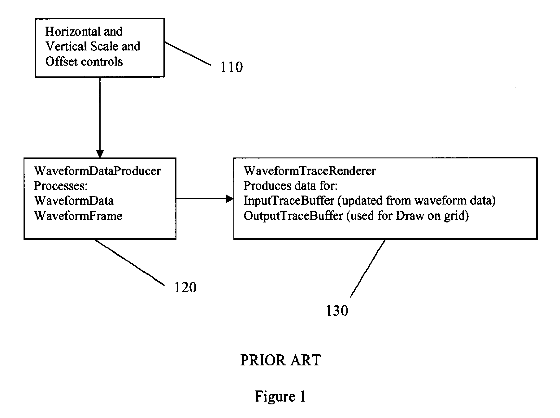
BACKGROUND OF THE INVENTION [0001]In a digital oscilloscope, a waveform trace is a fundamental software object that provides the user with a representative view of an acquired waveform data. Vertical and horizontal scale and offset controls affect the definition of the grid on which the waveform trace is displayed. The vertical (y) and horizontal (x) extents of the grid may be expressed as the waveform frame (in vertical and horizontal units of the waveform, e.g. Volts and Seconds) or in terms of display units (e.g. pixels).[0002]In such a digital oscilloscope, a waveform trace renderer has the responsibility to process the waveform data to produce appropriate data, and place this data in a buffer so that the data is properly scaled to the display. This may be necessary because the digital oscilloscope typically acquires many more data points than are displayable on any type of oscilloscope display, or for other reasons. Thus, the data is most often decimated appropriately so that t...

Claims


Application Information

Patent Timeline
Patent Type & Authority Applications(United States)
IPC IPC(8): G09G5/22
CPCG01R13/029G01R13/02
Inventor LIBBY, JONATHAN C.PATEL, HITESH
Owner TELEDYNE LECROY
Learn More