Thrust bearing assembly

a technology of thrust bearings and assemblies, applied in the direction of sliding contact bearings, elastic bearings, mechanical equipment, etc., can solve the problems of uneven load between individual balls, short service life, and high cost, and achieve the effect of avoiding costly finish grinding/lapping

Active Publication Date: 2009-10-29
CERADYNE
View PDF93 Cites 58 Cited by
  • Summary
  • Abstract
  • Description
  • Claims
  • Application Information

AI Technical Summary

Benefits of technology

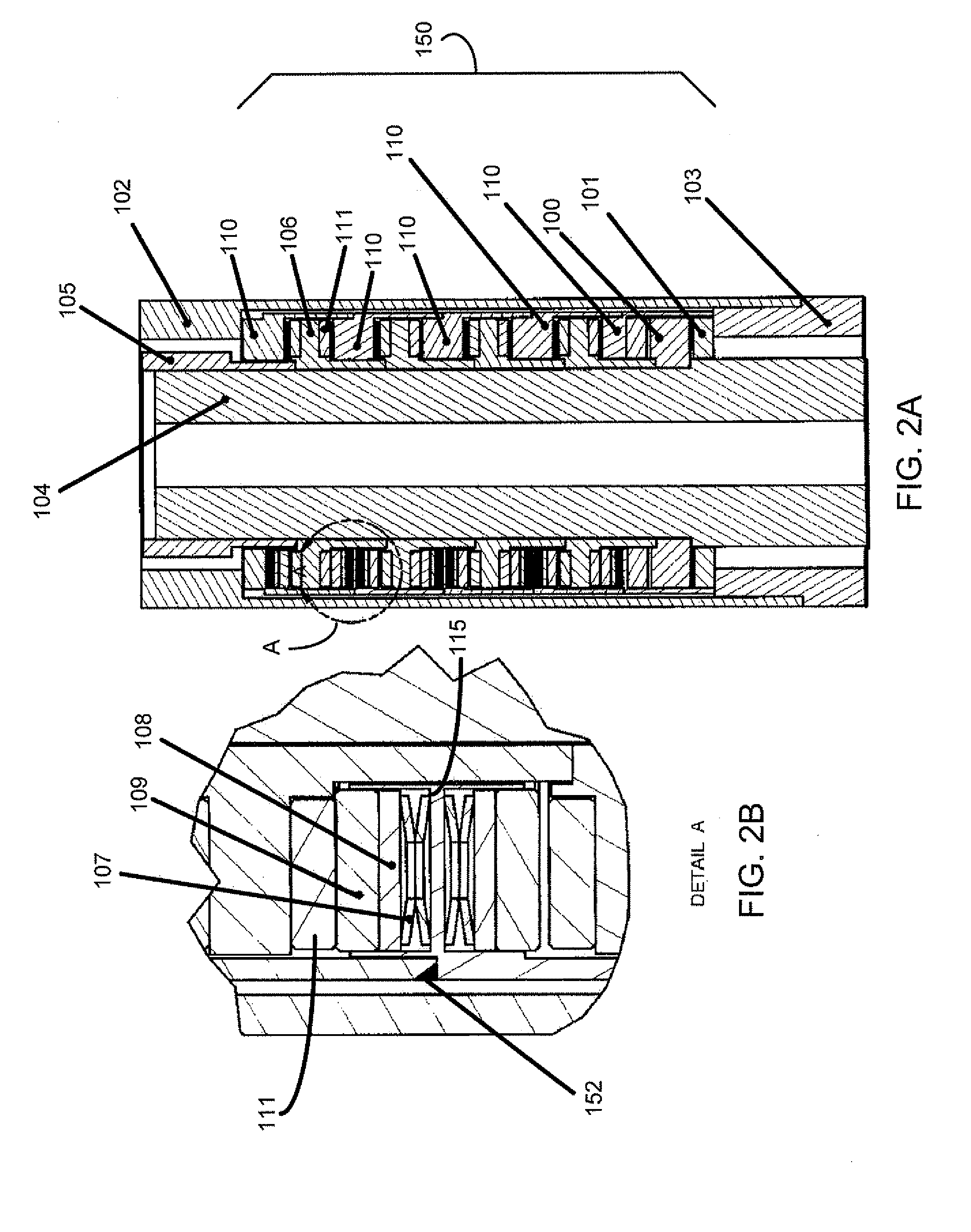
[0009]An embodiment of the present invention provides a hydrodynamic thrust bearing assembly in which each thrust pad is individually mounted on a deflection element. Rather than mounting an entire bearing having fixed pads on a resilient member (e.g., spring), the present invention resiliently mounts the individual thrust pads, thereby avoiding costly finish-grinding / lapping of the complete bearing assembly.
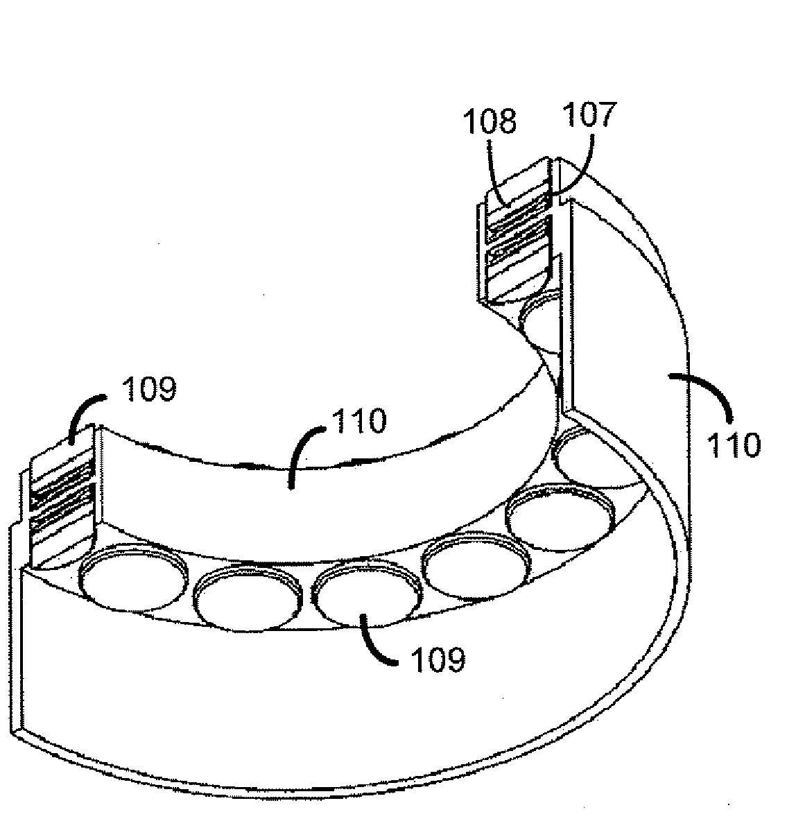
[0016]A further aspect of the present invention provides a pad holder assembly that secures a pad to the bearing carrier. The pad holder assembly comprises a pad holder and a fastener that attaches the pad holder to the bearing carrier. The pad holder can be made of metal carbide to which a silicone carbide pad is attached. In one implementation, the pad holder is cup shaped, with the pad disposed inside the cup and projecting above the cup. The fastener of the pad holder assembly can comprise a bolt disposed through a bolt opening in the bearing carrier. The bolt can be configured to move freely within the bolt opening such that the pad holder and pad can float above a surface of the bearing carrier. A deflection element can be disposed between the underside of the holder (i.e., the side of the holder opposite to the side on which the pad is disposed) and the surface of the bearing carrier. The deflection element provides a resistance and deflection appropriate for the deflection element to contact and deflect against the force of the bearing runner.
[0020]In a further aspect of the present invention, an opening that receives the fastener of a pad holder assembly has a shape other than a circular shape. For example, the opening could be slot shaped. The slot shape enables the pad and pad holder assembly to not only float in a direction perpendicular to the face of the bearing carrier, but also in a direction parallel to the face of the bearing carrier, as well as in any combination of those directions. Permitting the pads to travel in the parallel direction can accommodate manufacturing variances in closely spaced pads and pad holder assemblies, and can make assembly more convenient. Slots can also limit parallel travel during operation, which can provide advantages in properly locating the pads with respect to the bearing runner. As examples, a slot can extend radially from a center point of the bearing carrier or can extend along an are of the bearing carrier.

Problems solved by technology

Due to the high loads, pressure, and abrasive conditions, bearing life is typically only several hundred hours.
Rolling element-type bearings are not tolerant of abrasives and thus wear quickly when exposed to mud lubrication.
Once wear occurs, loads between the individual balls become uneven and wear rates accelerate.
For the oil-lubricated bearings, once the seals fail, wear occurs in a similar way.
These bearings, however, are extremely expensive and only marginally increase service life.

Method used


Image

  • Thrust bearing assembly
  • Thrust bearing assembly
  • Thrust bearing assembly

Examples


Embodiment Construction

[0059]Embodiments of thrust bearing assemblies are described in this detailed description of the invention. In this detailed description, for purposes of explanation, numerous specific details are set forth to provide a thorough understanding of embodiments of the present invention. One skilled in the art will appreciate, however, that embodiments of the present invention may be practiced without these specific details. In other instances, structures and devices are shown in schematic diagram form. Furthermore, one skilled in the art can readily appreciate that the specific sequences in which methods are presented and performed are illustrative and it is contemplated that the sequences can be varied and still remain within the spirit and scope of embodiments of the present invention.

[0060]An embodiment of the present invention provides a novel, longer life, higher capacity, lower cost hydrodynamic bearing that operates in, for example, a mud-lubricated or sealed oil bath-lubricated ...


PUM


Abstract

A thrust bearing assembly comprising a bearing runner and a bearing carrier, the carrier defining a plurality of thrust pad sites annularly around the carrier, with a thrust pad disposed at a site and with the carrier limiting movement of the thrust pad in a direction generally radial to the longitudinal axis of the runner while allowing the thrust pad to move in a direction generally parallel to the longitudinal axis. Though the range of movement is limited, the pads can tilt under load to form a hydrodynamic wedge as is known in the art. An embodiment comprises a bearing runner having a wear resistant face and a bearing carrier defining thrust pad sites disposed annularly around the carrier. In one implementation, at each site, a deflection element (e.g., Belleville washer) is disposed in a cavity and a pad is disposed over the deflection element. The pad can be at least partially disposed within the cavity. The wear resistant face contacts the pad. Another embodiment rigidly connects pads disposed oil opposite sides of a stationary bearing carrier. Another embodiment attaches pads to a bearing carrier using pad holder assemblies.

Description

[0001]This application claims the benefit of U.S. Provisional Application No. 61 / 049,632, filed May 1, 2008, which is herein incorporated by reference in its entirety. This application is also a continuation-in-part of U.S. patent application Ser. No. 11 / 948,552, filed Nov. 30, 2007, which is a continuation-in-part of U.S. patent application Ser. No. 11 / 148,178, filed Jun. 9, 2005, now U.S. Pat. No. 7,306,059, issued Dec. 11, 2007, all of which are herein incorporated by reference in their entirety.BACKGROUND[0002]1. Field of the Invention[0003]The present invention relates to thrust bearing assemblies, and more particularly to a hydrodynamic thrust bearing assembly having thrust pads mounted on one or more resilient deflection elements, such as Belleville washers.[0004]2. Background of the Invention[0005]Most conventional downhole drilling motors use rolling element-type bearings, such as ball rollers or angular contact rollers. U.S. Pat. No. 5,074,681 to Turner et al. discloses an...

Claims


Application Information

Patent Timeline
Patent Type & Authority Applications(United States)
IPC IPC(8): F16C32/06F16C33/02
CPCE21B4/003E21B4/02F16C33/26F16C27/08F16C32/0692F16C17/06F16C33/108F16C41/02F16C2352/00
Inventor IDE, RUSSELL D.IDE, RUSSELL C.
Owner CERADYNE
Why Eureka
Try Eureka