

Low profile rear tip for inflatable penile prostheses
a penile prosthesis and low-profile technology, applied in the field of inflatable penile prosthesis, can solve the problems of patient discomfort during operation, inability to satisfactorily mitigate, and relatively inefficient and costly construction
- Summary
- Abstract
- Description
- Claims
- Application Information
AI Technical Summary
Benefits of technology
Problems solved by technology
Method used
Image

Examples
Embodiment Construction
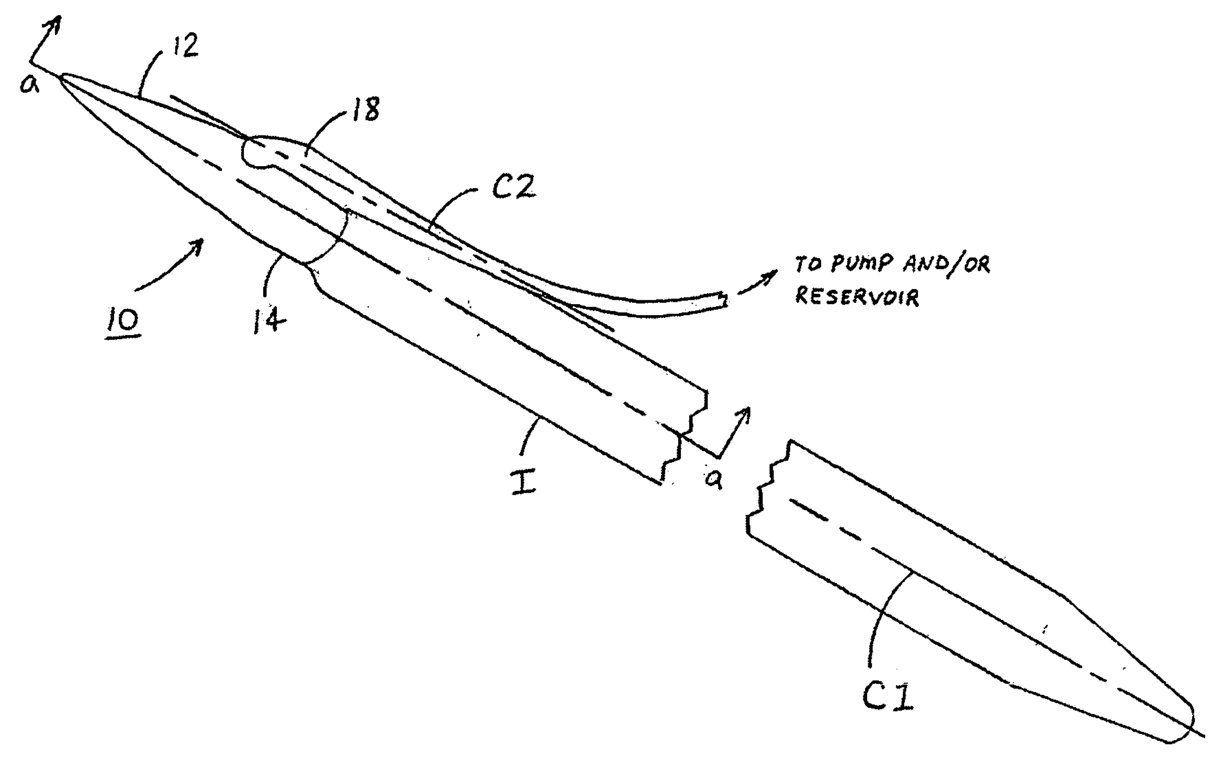
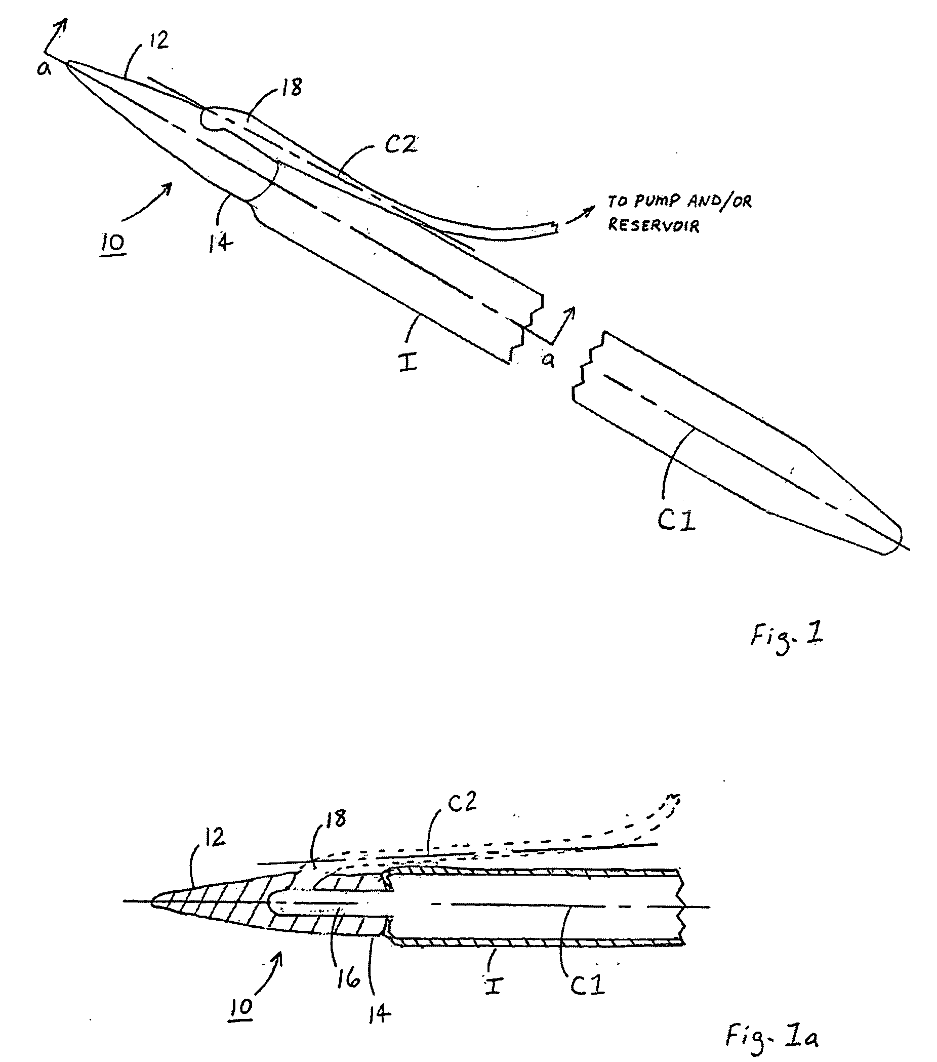
[0012]Illustrated in FIGS. 1 and 1a is an example of a low profile rear tip 10 (hereinafter, “rear tip 10”) for inflatable penile prostheses of the present invention, depicted as being connected to an IPP cylinder I. In this example, rear tip 10 could include a proximal end portion 12, a distal end portion 14 capable of being coupled to cylinder I along a major longitudinal axis C1 between proximal end portion 12, distal end portion 14, and cylinder I. Rear tip 10 could also include a fluid chamber 16 in distal end portion 14, with chamber 16 being in fluid communication with cylinder I. Rear tip 10 could further include a fluid conduit 18 having a strain relief portion and a tubing junction, integrally formed with distal end portion 14. Fluid conduit 18 could have a minor longitudinal axis C2, and be in fluid communication with fluid chamber 16 in distal end portion 14. Rear tip 10 could be constructed so that an elevation or angle between minor longitudinal axis C2 and major longi...
PUM
 Abstract
Description
Claims
Application Information