Pivoting Device for a Centrifugal Traction Assembly of a Vehicle

Active Publication Date: 2009-11-05
VBG GRUP PABL
View PDF7 Cites 0 Cited by
  • Summary
  • Abstract
  • Description
  • Claims
  • Application Information

AI Technical Summary

Benefits of technology

[0015]An advantage according to the concept of the present invention is that the device wi

Problems solved by technology

Smaller trucks does usually not have pneumatic or hydraulic systems, hence these systems can not be used to operate an anti-skid device.
Drawbacks with prior art anti-skid devices, which are equipped with damping spring for unintentional movements of the operating arm, are that they are

Method used


Image

  • Pivoting Device for a Centrifugal Traction Assembly of a Vehicle
  • Pivoting Device for a Centrifugal Traction Assembly of a Vehicle
  • Pivoting Device for a Centrifugal Traction Assembly of a Vehicle

Examples


Embodiment Construction

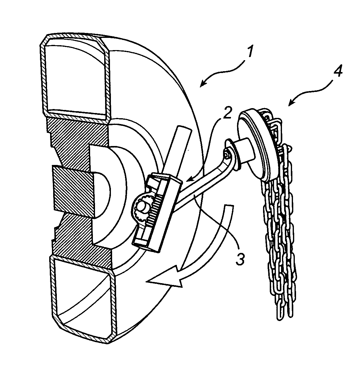
[0022]An operating device 2 according to an embodiment of the invention, will now be described in relation to the figures.

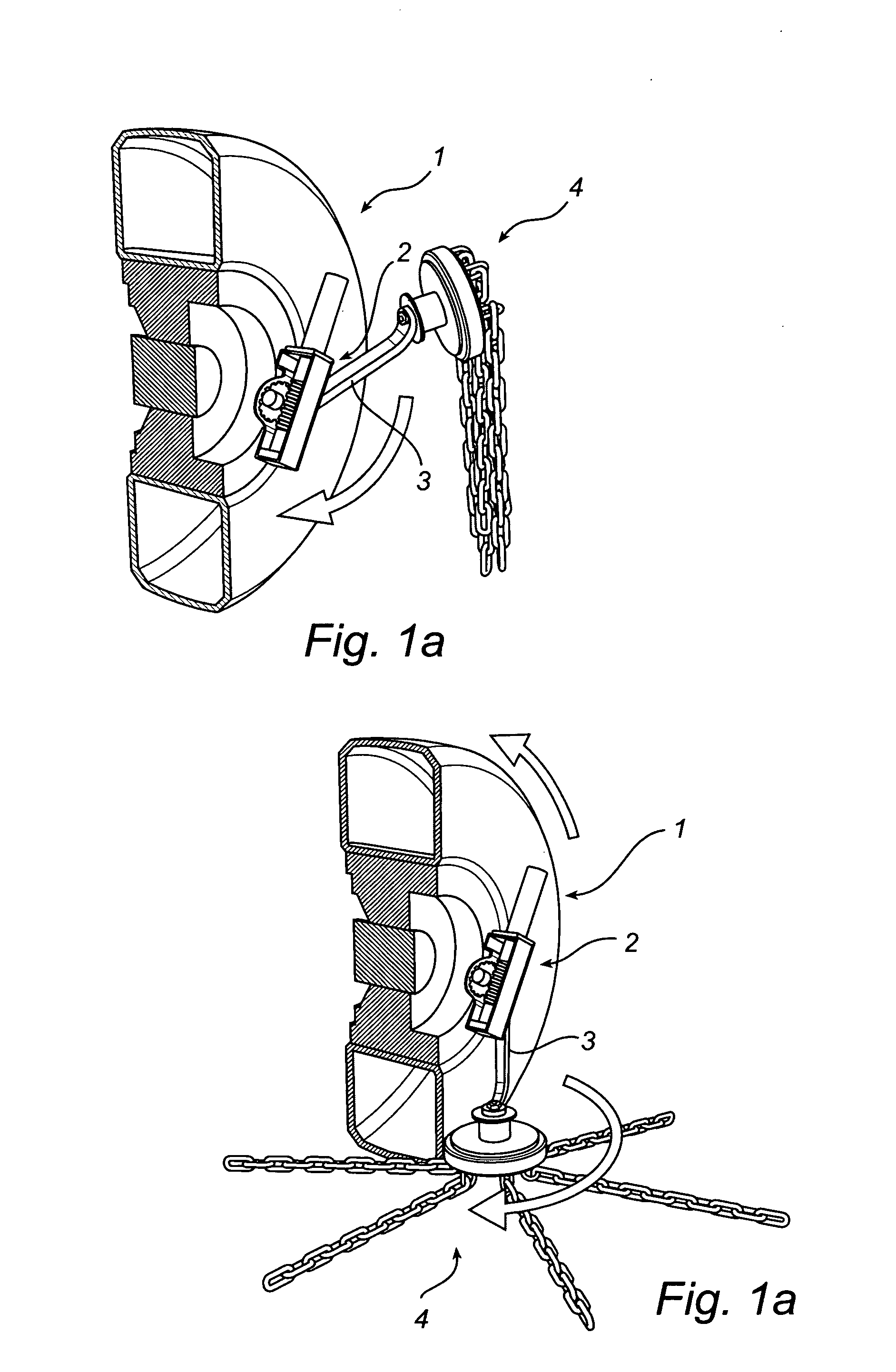
[0023]The anti-skid arrangement 1 illustrated in FIG. 1 is used for engagement with a wheel of a vehicle, to be activated when the ground is slippery, providing an increased friction between the wheel and the ground. It comprises a friction means 4 carried by an operating arm 3 movable by the operating device 2 between an active and passive position. The friction means 4 is constituted of a wheel with a number of chains, but any kind of friction means could be used.

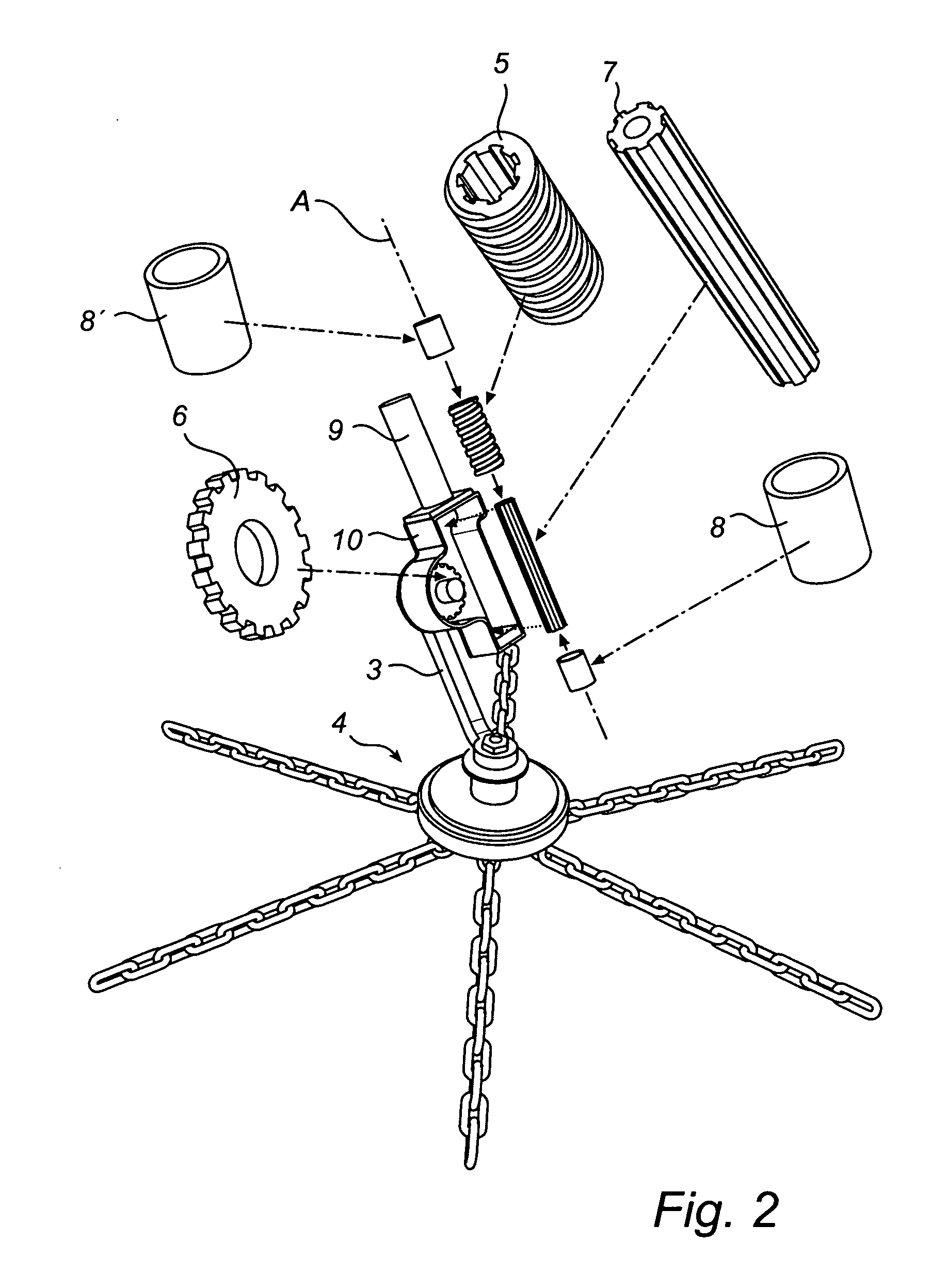
[0024]The operating device 2 here comprises a worm transmission, driven by an electric motor 9, for operation of the operating arm 3 of the anti-skid mechanism between passive (FIG. 1a) and active position (FIG. 1b). The electric motor 9 drives a drive shaft, here a splineshaft 7, which transfer the rotation to the worm 5 via internal splines. As shown in FIG. 2 there is a tube 8, 8′ of a resilient mat...


PUM


Abstract

The invention discloses an anti-skid mechanism operating device (1) for vehicles comprising an operating unit (2) and an operating arm (3) pivotally supported thereby and intended to carry a rotary anti-skid device (4) and to operate the latter between an active and a passive position. The operating device (2) comprises a worm gear (6) and a driven worm (5) adapted to engage said worm gear (6) for operation of the operating arm (3). The driven worm (5) is resiliently displaceable along an axis (A) of said worm (5).

Description

FIELD OF THE INVENTION[0001]The present invention relates to an operating device for a vehicle anti-skid arrangement comprising an operating unit and an operating arm pivotally supported thereby and intended to carry a rotary anti-skid device and to operate the latter between an active and a passive position.TECHNICAL BACKGROUND[0002]Smaller trucks does usually not have pneumatic or hydraulic systems, hence these systems can not be used to operate an anti-skid device.[0003]Drawbacks with prior art anti-skid devices, which are equipped with damping spring for unintentional movements of the operating arm, are that they are space consuming and will limit the ground clearance of the vehicle. There could also occur impacts or problems causing damage to the device. There is for example devices operated by a wire, which also will act as a spring, having the disadvantages of corrosion and problems during mounting.SUMMARY OF THE INVENTION[0004]One object of the present invention is to provid...

Claims


Application Information

Patent Timeline
IPC IPC(8): F16H25/18B60B39/00
CPCY10T74/18792B60B39/006
Inventor HOLMGREN, LARS
Owner VBG GRUP PABL
Why Eureka
Try Eureka